
NewsNEWCENTER
Featured products

Contact Us
The circuit breaker – the first line of defense in a power distribution system. Have you chosen the right one?
2026-07-17Introduction:
Among all components in a low-voltage distribution cabinet, none is more critical than the circuit breaker. It serves as the “last physical line of defense” for the entire power distribution system—should a short circuit occur and the breaker fails to interrupt the fault current within milliseconds, the consequences would extend far beyond damaging a single cable, potentially affecting the entire transformer winding, a set of expensive busbars, or even triggering a fire.
To understand circuit breakers, it is essential to first grasp their classification logic. Low-voltage circuit breakers (also known as automatic circuit breakers) are categorized into three main types based on structure: universal circuit breakers (Air Circuit Breaker, ACB), molded case circuit breakers (Molded Case Circuit Breaker, MCCB), and miniature circuit breakers (Miniature Circuit Breaker, MCB). The differences among them extend beyond size; the fundamental distinctions lie in their respective positions within power distribution systems and the protection functions they perform.
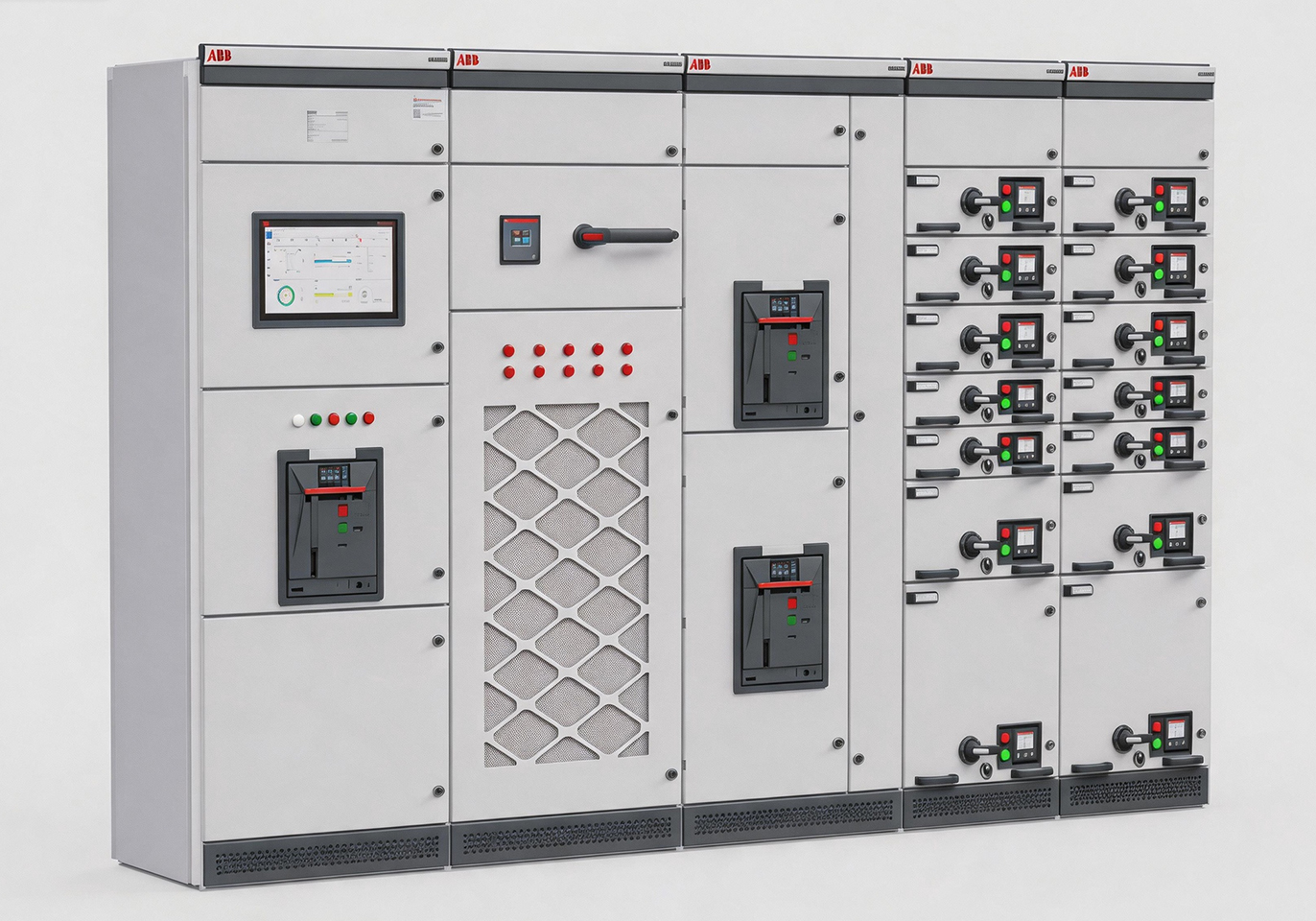
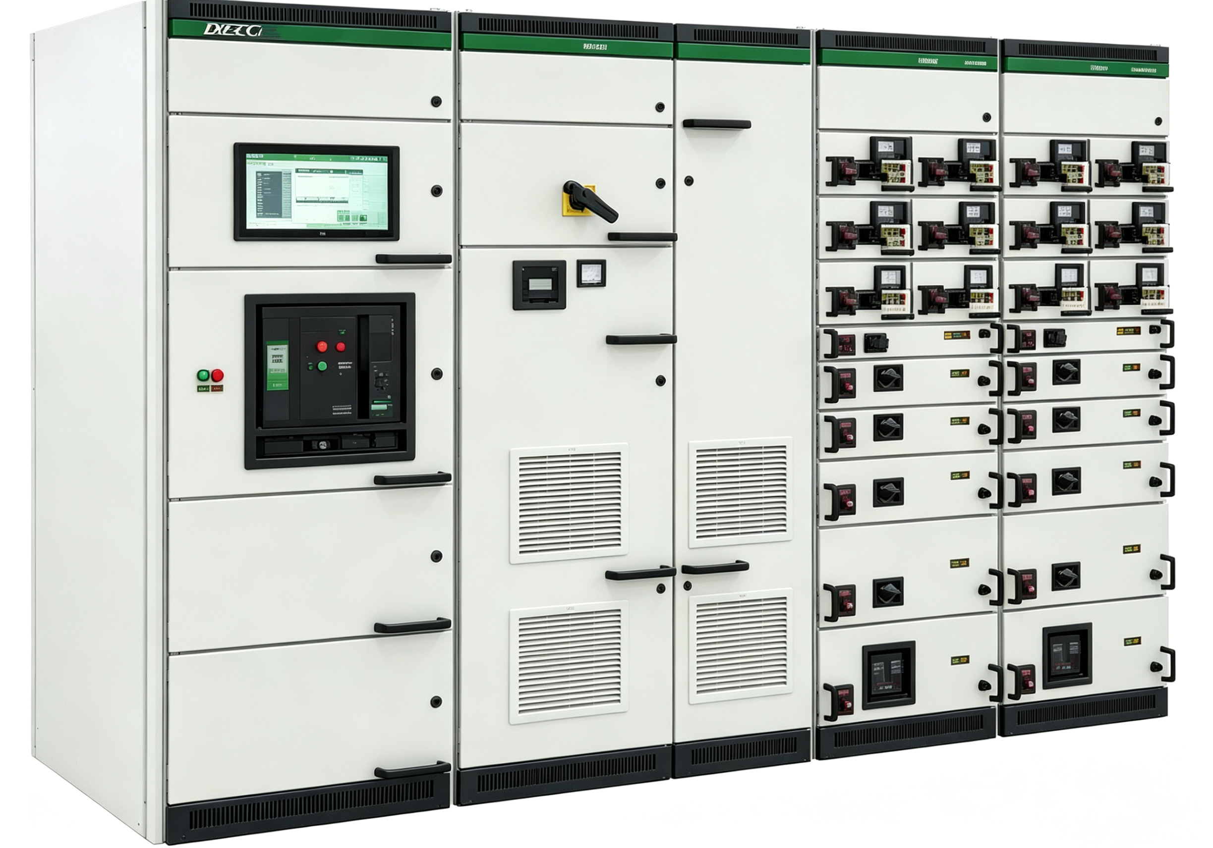
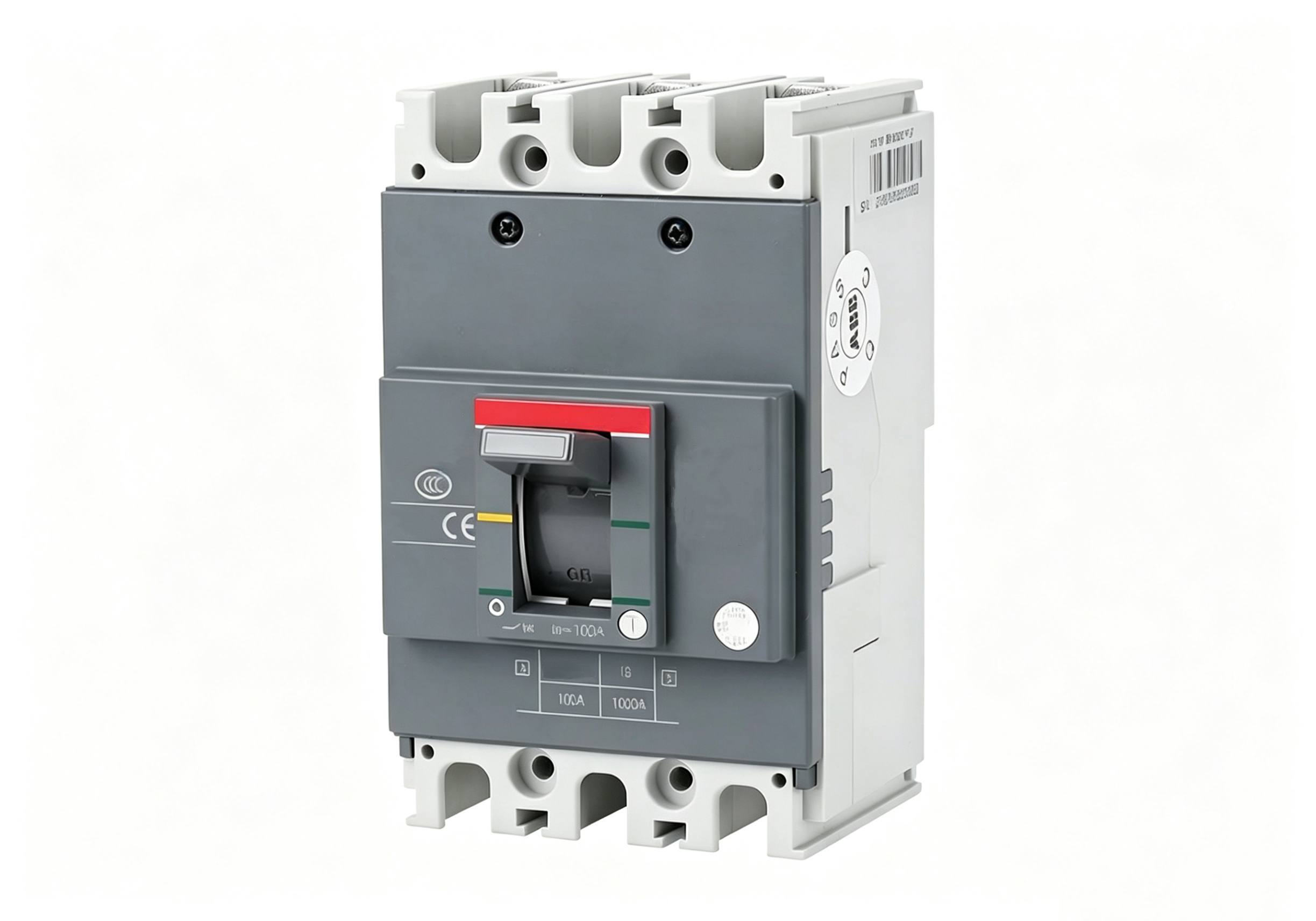
An ACB is installed at the “main switch” position on the low-voltage output side of a transformer, responsible for protecting the incoming lines of the entire power distribution system; it represents the highest-level protection device with the greatest capacity and breaking capability. An MCCB is typically mounted on the outgoing circuits of a distribution cabinet, safeguarding each feeder line or large equipment connected to it and performing secondary distribution and protection functions. However, its limitation lies in its fixed housing rating, requiring complete replacement for capacity expansion. Thermal-magnetic trip units are significantly affected by ambient temperature and must operate at reduced ratings in high-temperature environments. In applications requiring frequent operation, their mechanical lifespan generally ranges from 10,000 to 20,000 cycles, which is shorter than that of an ACB.
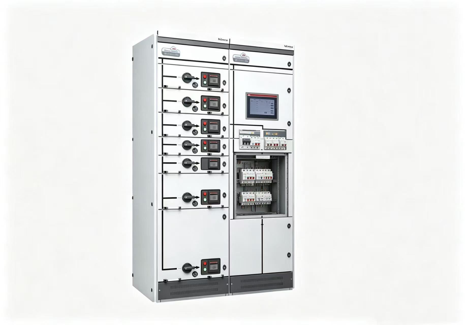
The MCB serves as the “sentinel” of the end circuit. A typical single-pole miniature circuit breaker has a thickness of 18 mm (i.e., 1 module = 18 mm) and consists of a tripping mechanism, actuating components, contact system, and arc extinction chamber. It employs current-limiting interruption technology, utilizing the short-circuit fault current to rapidly open the contacts while causing the arc voltage between them to rise sharply, thereby limiting the short-circuit current. From the lighting circuit downstream of the MCCB to the computer socket on the desk, it provides protection throughout this entire path.
Three-level circuit breakers must achieve selective coordination: when a fault occurs at a lower level, only the circuit breaker adjacent to the fault point trips, while the higher-level breaker continues supplying power normally, thereby minimizing the scope of power outage. An improperly designed selection scheme may cause a short circuit at a single terminal socket to trigger a complete building-wide power failure; its limitation lies in limited breaking capacity (up to 15 kA), making it unsuitable for installation in main distribution circuits with high expected short-circuit currents. With a rated current limit of only 125 A, it is not suitable for heavy loads. In environments with high harmonic content (e.g., those with extensive LED lighting or UPS equipment), conventional MCBs may trip due to overheating caused by high-frequency currents. The mechanical lifespan is approximately 10,000 cycles, and they should be used cautiously under frequent operating conditions.
Next, let’s discuss how to select a circuit breaker for your project. There are four key parameters to evaluate when choosing a circuit breaker.
Rated current. This is the most fundamental requirement: the circuit breaker’s rated current must be greater than or equal to the calculated line current. However, note that “greater than or equal to” does not imply “the higher the better.” If the selected rated current is too high, the circuit breaker becomes insensitive to overloads and may fail to trip when the line breaks; if it is too low, frequent tripping occurs during normal operation. It is generally recommended that the load current not exceed 80% of the circuit breaker’s rated current to allow for startup surges. Additionally, when ambient temperature exceeds 40°C, the manufacturer’s rating reduction curve must be consulted for correction.
Breaking capacity is the parameter most frequently underestimated in circuit breaker selection. It refers to the maximum short-circuit current value that a circuit breaker can safely interrupt. If the expected short-circuit current at the installation point exceeds the breaker’s breaking capacity, the device may explode or experience contact welding during fault interruption attempts. Calculating the expected short-circuit current requires consideration of transformer capacity, impedance voltage, line length, and cross-sectional area. Circuit breakers near transformers should prioritize high-breaking-capacity models (e.g., above 25 kA), while those at branch ends may employ lower capacities (e.g., 6 kA). A critical detail often overlooked is that actual breaking capacity should be evaluated using two parameters: Icu (limiting short-circuit breaking capacity) and Ics (operating short-circuit breaking capacity). Ics represents the breaker’s ability to continue carrying rated current and functioning normally after completing a short-circuit interruption; for systems requiring high power continuity, Ics must not fall below the expected short-circuit current.
The trip curve is the key parameter determining when a circuit breaker should trip and when it should not. The three most common types are: Type B (tripping at 3–5 times the rated current) is suitable for electronic equipment, long-distance lines, and other applications requiring high sensitivity; Type C (5–10 times the rated current) is the most widely used general-purpose curve, applicable to lighting, heating systems, and general inductive loads; Type D (10–20 times the rated current) is specifically designed for devices such as motors where the starting current can reach 6–8 times the rated current, ensuring effective short-circuit protection while withstanding starting surges. If a large water pump is equipped with a Type C circuit breaker, it will approach the trip threshold during each startup; conversely, if a lighting circuit uses a Type D circuit breaker, it may fail to trip promptly when a short circuit actually occurs—the consequences would be evident.
Number of phases: Use 3P for three-phase three-wire systems; use 4P for three-phase four-wire systems requiring N-line protection; use 2P for single-phase systems (by disconnecting both the phase and N lines to ensure maintenance safety). Using 1P only disconnects the phase line—while cost-effective, it leaves the N line energized during TN-S system maintenance, posing safety risks.
Finally, the most common consequence of selecting the wrong circuit breaker is not “non-functional,” but rather “it appears functional until a fault occurs reveals the defect.” A terminal socket circuit was equipped with an MCB rated for 6 kA, installed very close to the transformer; the actual short-circuit current was as high as 12 kA. In such conditions, the circuit breaker proves utterly ineffective during a genuine short circuit.
Final four-step selection summary method:
1Determine the series number: 1P/2P/3P/4P, matching the circuit configuration and grounding method. 2. Determine the rated current: The circuit breaker’s rated current must be ≥ the calculated line current, with capacity reduction factors considered (use reduced capacity when ambient temperature exceeds 40°C). 3. Determine the breaking capacity: The circuit breaker’s rated operating short-circuit breaking capacity (Ics) must be ≥ the expected maximum short-circuit current at the installation point. 4. Determine the trip characteristics: Select curve B for lighting/resistance loads, curve C for general distribution systems, and curve D for high-impulse-current equipment.