
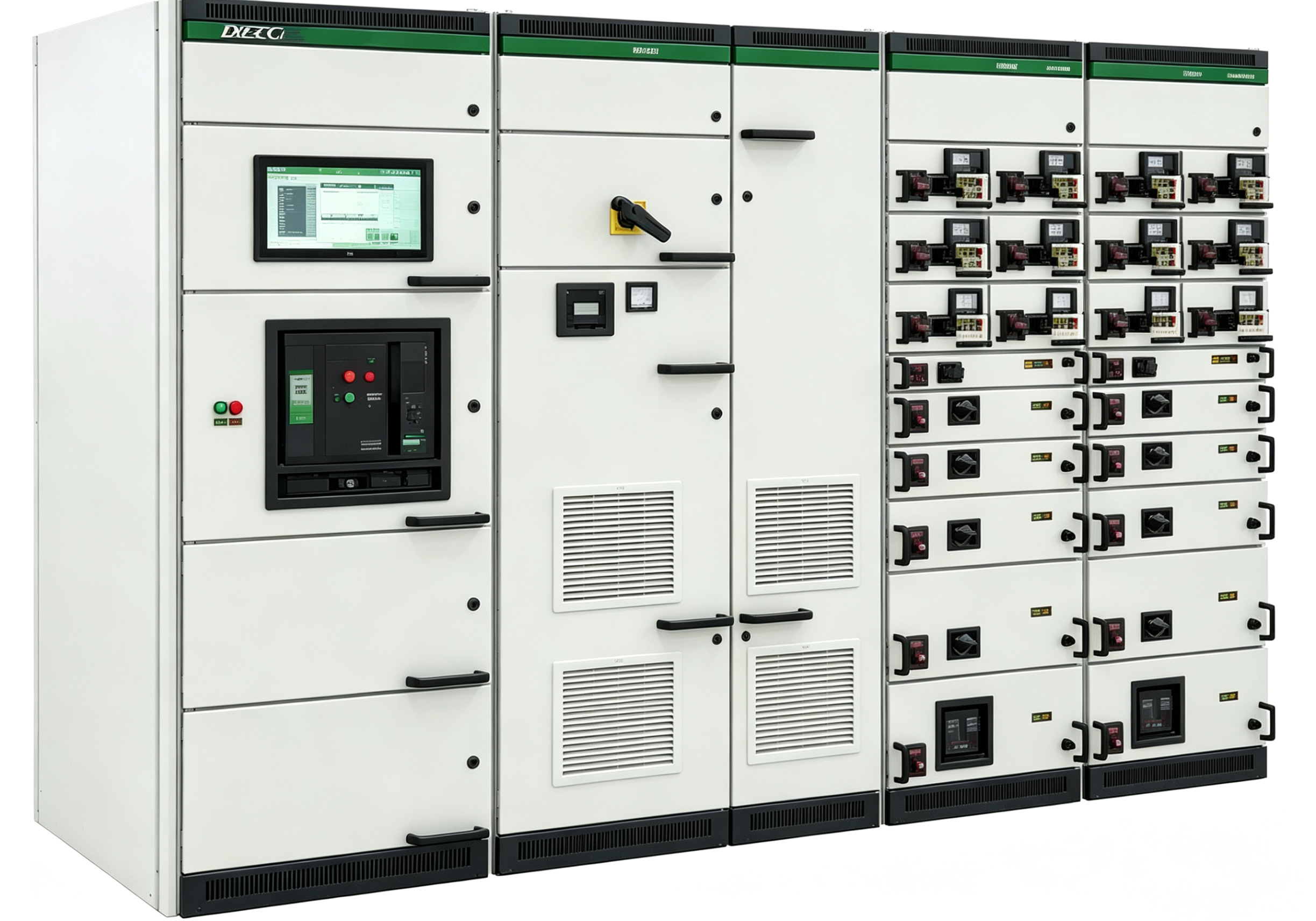
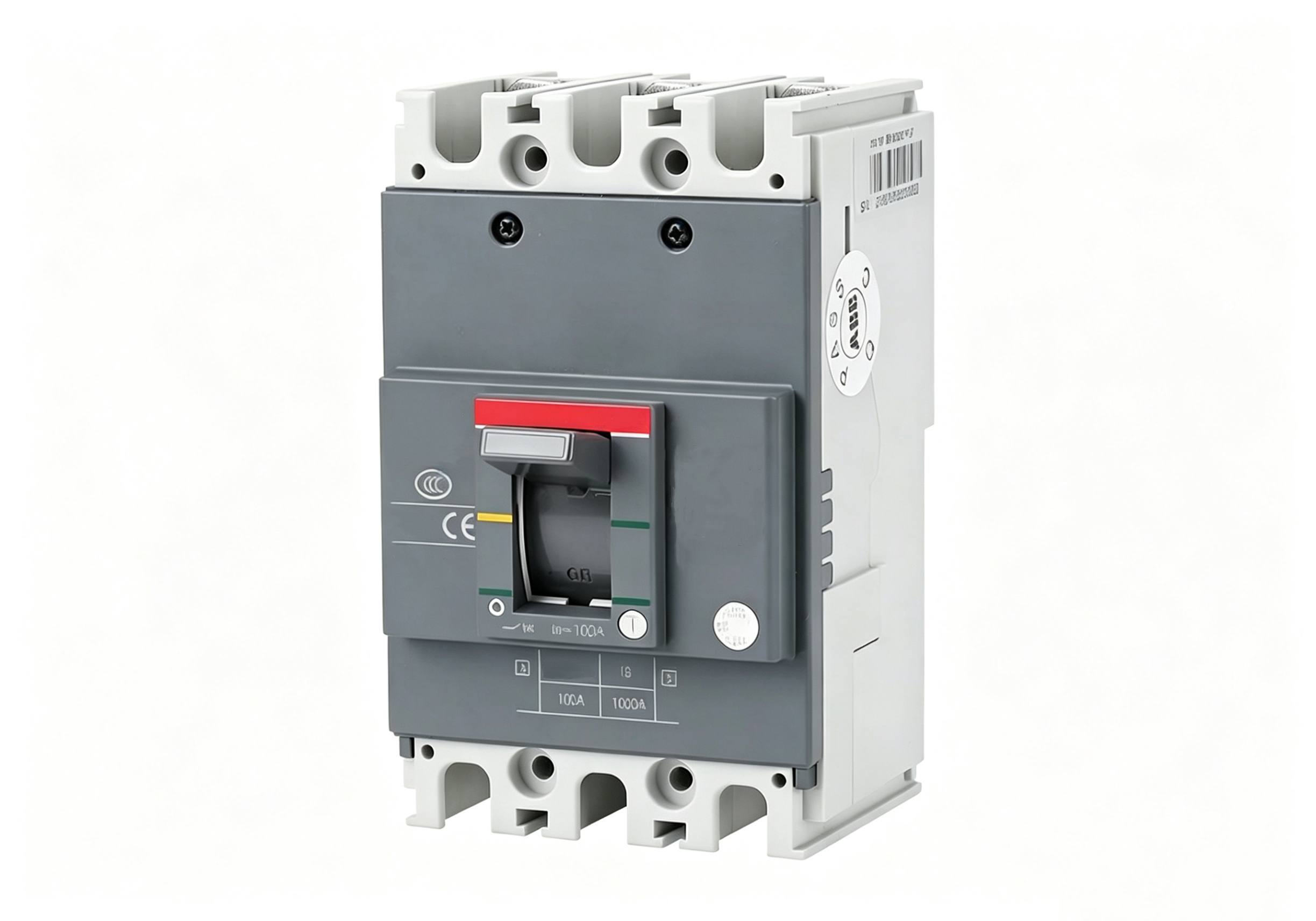

When a distribution system fault occurs, time is money — every extra minute of outage may cost thousands in production losses, lost data in a data center, or delayed care for a hospital patient. Yet when faults happen, many on‑site personnel freeze — unsure where to start, they check here and there, wasting precious time. In fact, distribution system troubleshooting follows a proven methodology — follow it, and you can pinpoint the fault in the shortest possible time and restore power quickly. This article is in two parts: the first covers the rapid troubleshooting steps after a fault occurs; the second explains the Automatic Transfer Switch (ATS) — how it helps you achieve “outage without downtime.”
Part One: The “Golden Ten Minutes” of Fault Diagnosis
The efficiency of the first ten minutes after a fault determines the entire recovery time. Here are six steps in priority order — your “troubleshooting roadmap.”
Step 1: Determine the fault scope — “total blackout” or “partial blackout”?
This is the first priority. Walk to the electrical room and check the incoming panel’s meters and indicators. If the incoming panel shows “no voltage” (voltmeter at zero, all indicators off), the entire system is down — the problem is upstream (transformer, high‑voltage side, or utility). If the incoming panel is live but a specific busbar section or outgoing circuits are dead, the problem is internal — a breaker has tripped, or a busbar section has faulted. Method: check the incoming panel and bus‑tie panel, then outgoing panel indicators. Incoming dead → upstream fault; incoming live but outgoing tripped → internal fault.
Step 2: Find the “trip signal” — which breaker tripped?
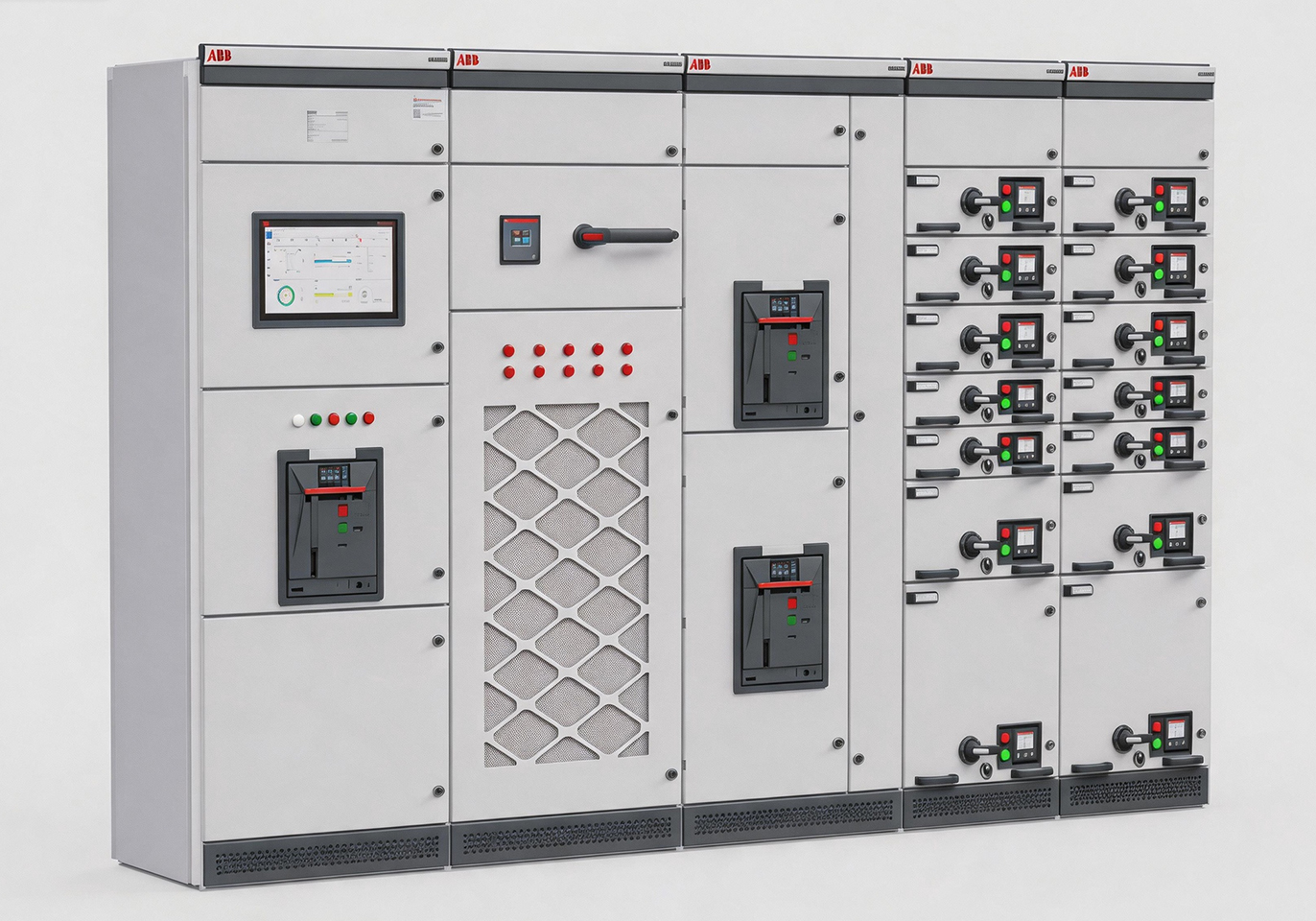
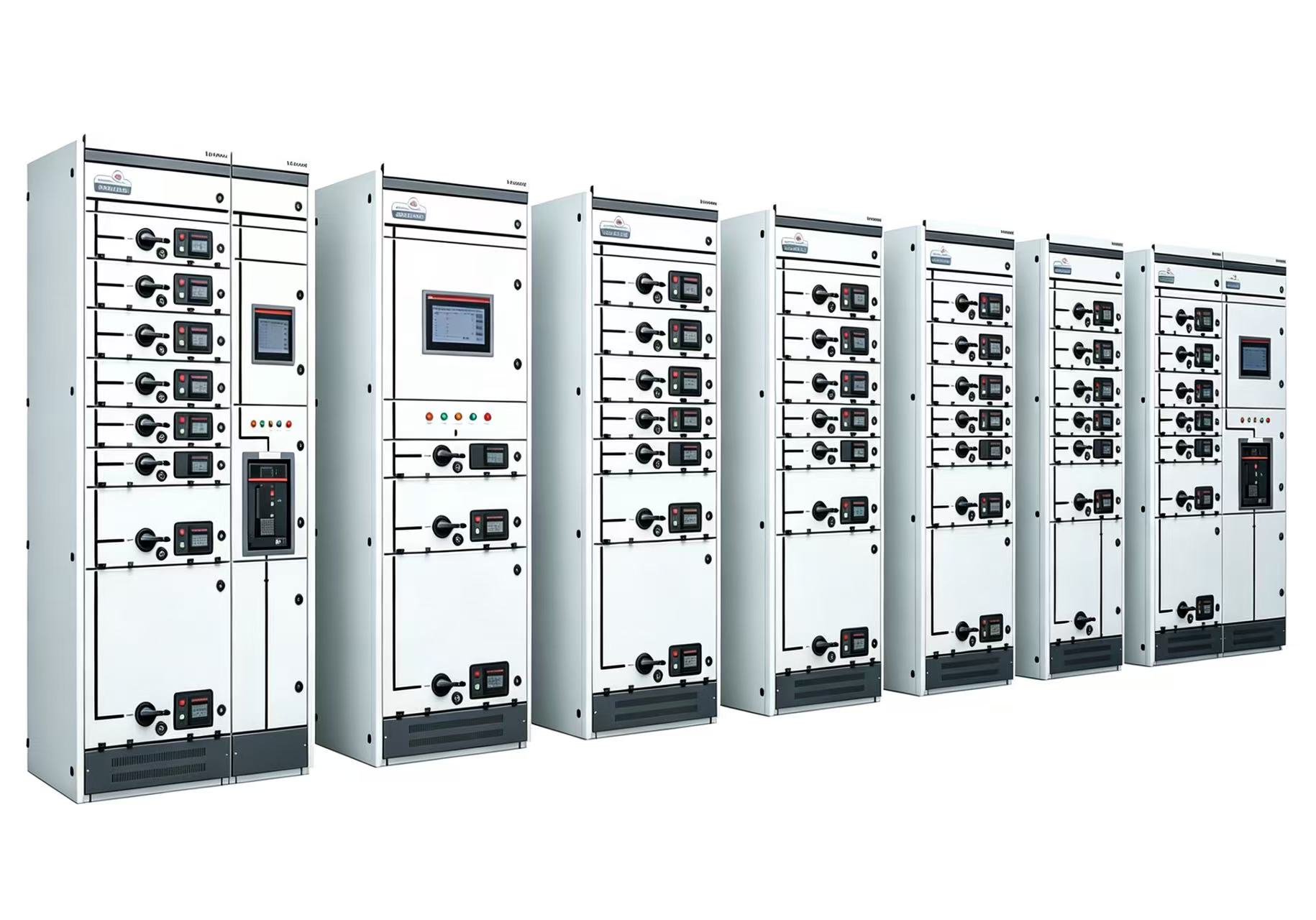
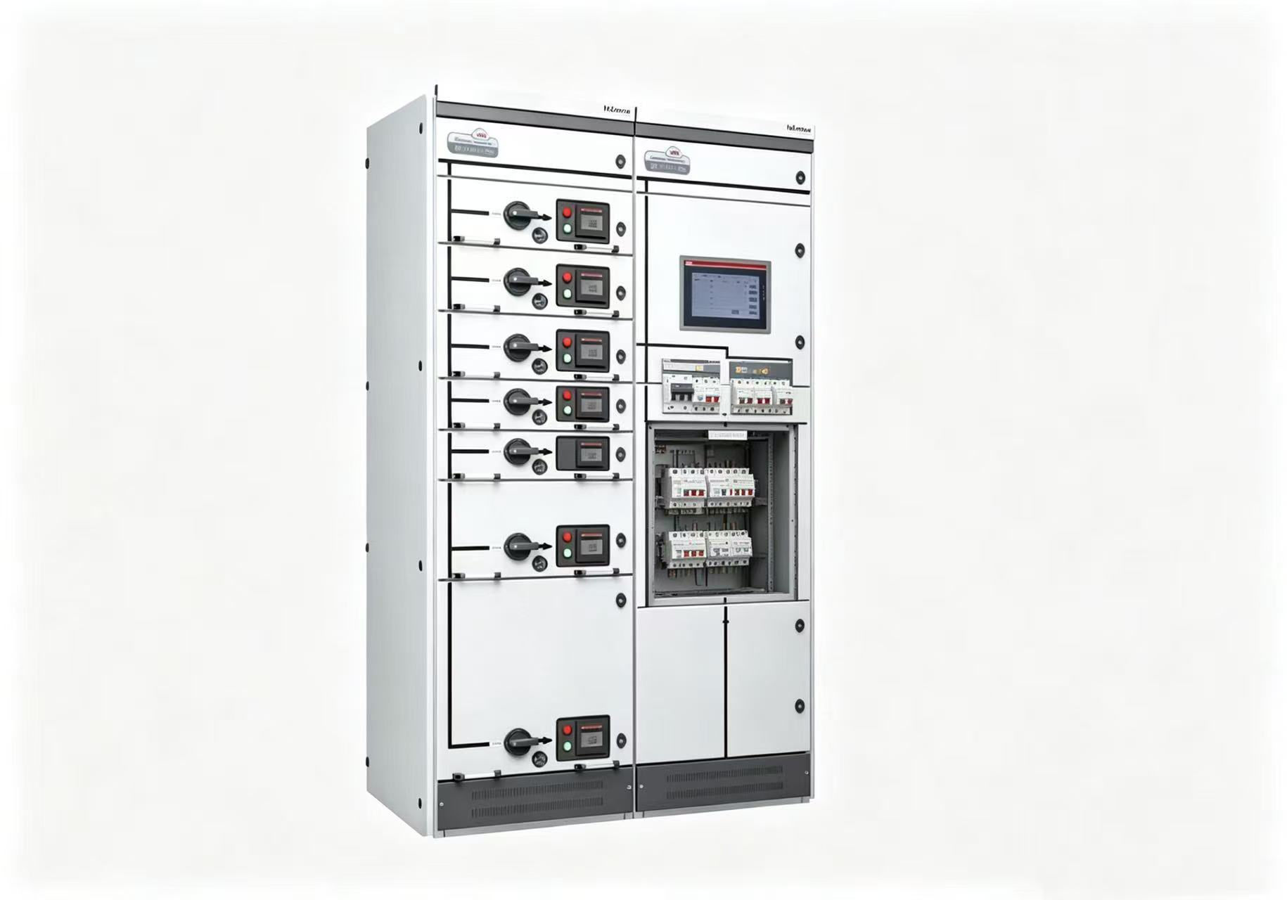
Once the scope is determined, find the trip point. Modern switchgear has position indicators (open/closed) and fault indicators (trip indication) on each breaker. Starting from the busbar, follow the dead zone downstream until you find a breaker in the “open” position with its fault indicator popped or lit.
Key tip: Don’t rely solely on the “closed” indicator light — it may be off because control power is lost, even though the breaker is still closed. Correct method: check the breaker’s mechanical position indicator (red = closed, green = open) — this is always reliable.
Step 3: Check the protection relay’s “fault record”
Modern switchgear often has intelligent protection relays (such as microprocessor‑based relays) with fault recording — storing the fault type, magnitude, and time. Once you find the tripped breaker, check its protection relay display or recorder — it will tell you whether the trip was caused by overload, short circuit, earth fault, or something else. This dictates the next investigation direction: overload → check the load; short circuit → check insulation; earth fault → check cables and insulation monitoring.
Step 4: Smell, look, measure — quickly pinpoint the fault
Once you know the fault type, investigate directionally. Use “smell, look, measure” to locate the fault:
-
Smell: Open the affected switchgear — any burning smell? The strongest odour often marks the fault location.
-
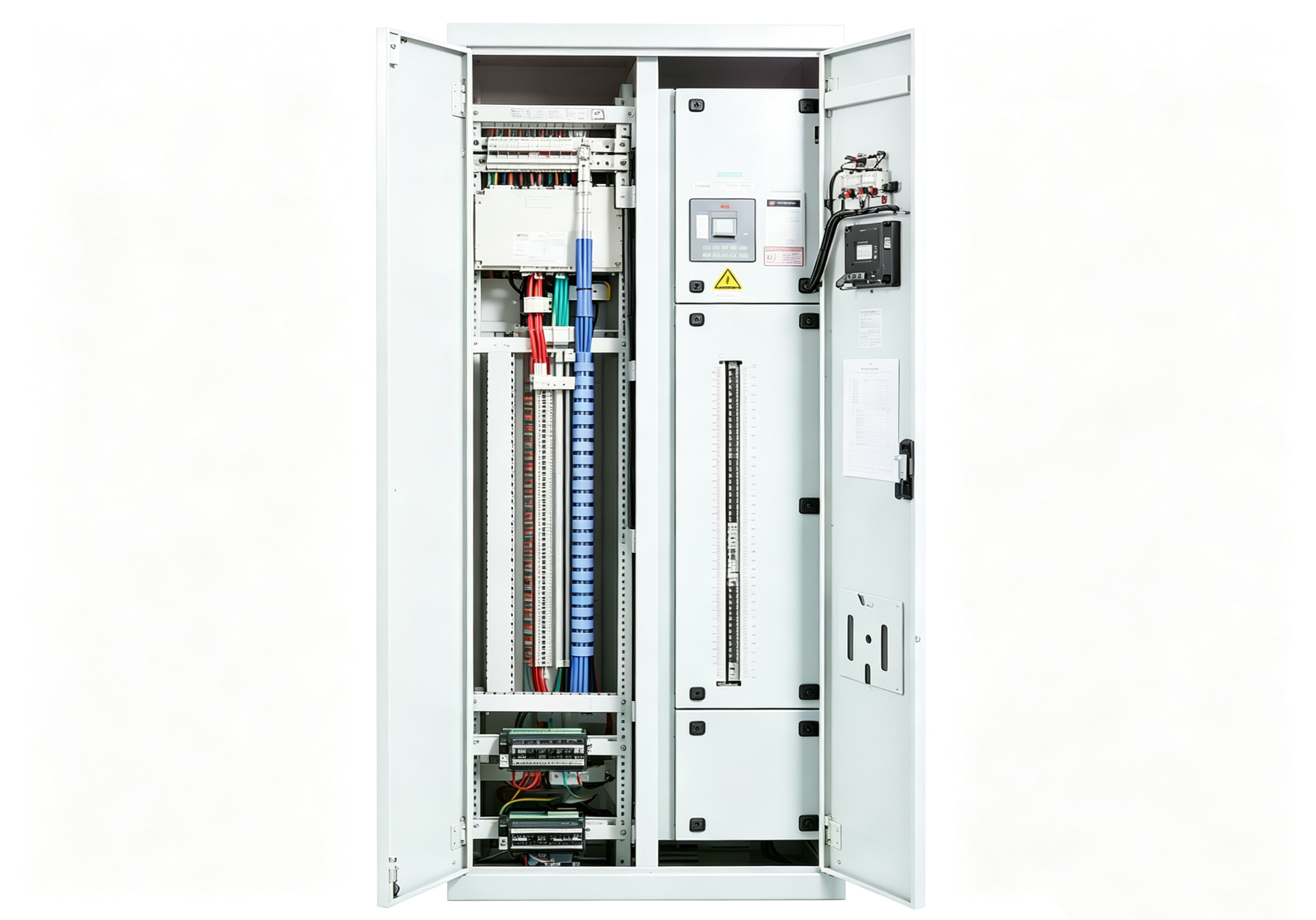
Look: Check breaker terminals for blackening, cable insulation for damage, the cabinet interior for foreign objects, and busbars for discharge marks.
-
Measure: Use an infrared thermometer to scan connection points in the tripped circuit — any point significantly hotter than surroundings may have been a pre‑existing隐患.
Step 5: Check for “hidden causes” — don’t be fooled by surface indications
Sometimes the apparent trip cause isn’t the root cause. For example: a breaker shows “overload trip” but actual load current is within limits — the thermal element may have aged and drifted. A breaker shows “short‑circuit trip” but no short circuit is found — it could be a nuisance trip from an upstream fault, or someone accidentally closed the earthing switch. Don’t rely solely on the relay alarm — combine it with on‑site inspection, system configuration, and operation logs for a comprehensive assessment.
Step 6: Isolate the fault and restore power
Once the fault point is identified and cleared, proceed with restoration following the “five‑prevention” and safety procedures. The key here is: don’t restore all loads at once — start with an unloaded or lightly loaded circuit, verify system stability, then gradually restore other loads. Step‑by‑step restoration avoids a second trip from inrush current.
Part Two: ATS — Automatic Transfer Switch, Your “Automatic Lifesaver” During Outages
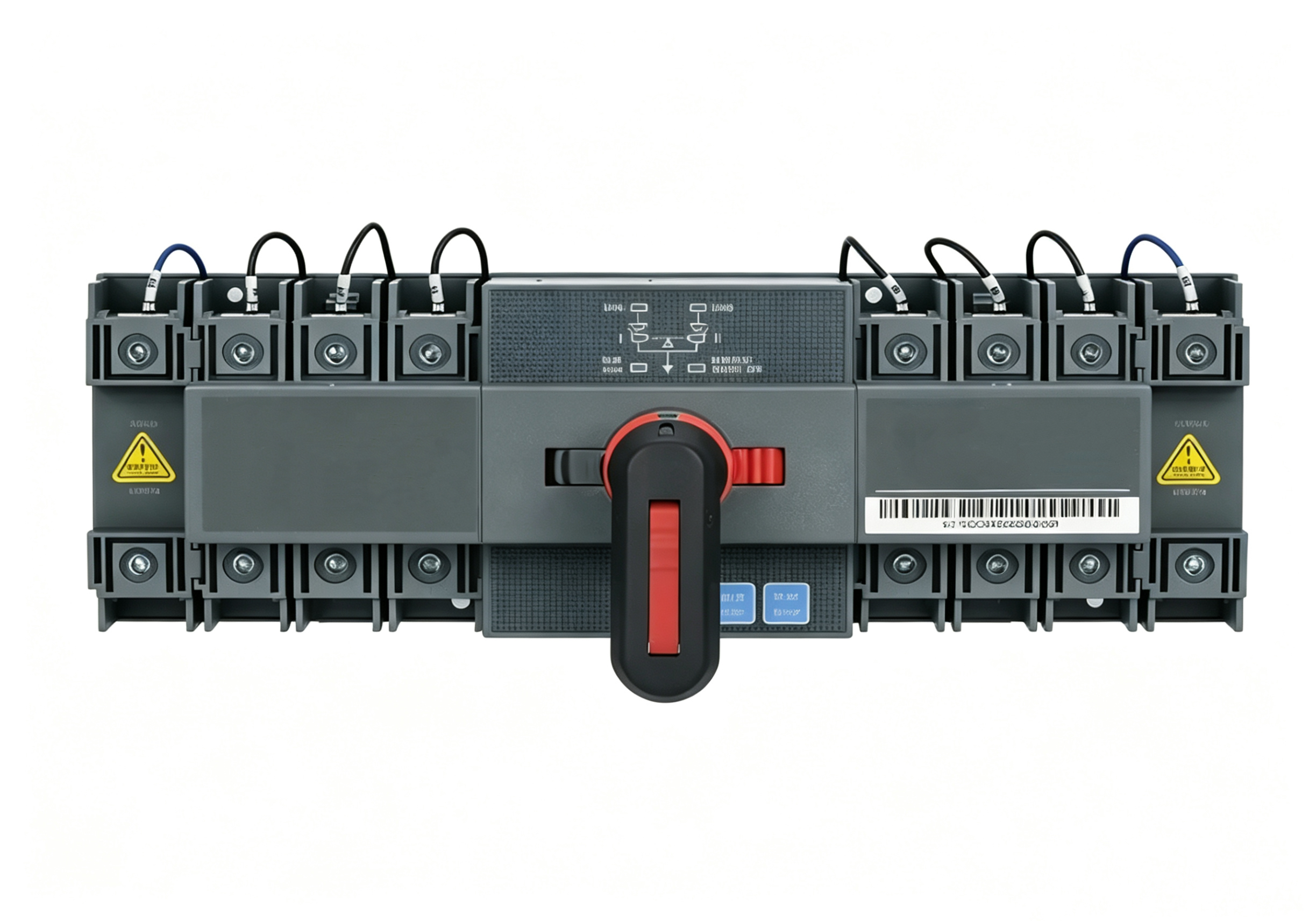
For facilities like hospitals, data centers, and continuous production lines where “not a second of downtime” is acceptable, manual fault diagnosis and restoration take too long. That’s where the Automatic Transfer Switch (ATS) comes in.
What is an ATS?
An ATS is an automatic device that, upon detecting the loss of the normal power supply, automatically transfers the load to a backup power source. In simple terms: it “decides” to switch to the backup supply when the main supply fails, entirely without human intervention.
The “Three Components” of an ATS
A complete ATS system consists of:
-
Sensing elements: Voltage and current transformers continuously monitoring the normal supply. When the supply loses voltage, the sensing element sends a start signal.
-
Logic unit: The “brain” of the ATS. Upon receiving the loss‑of‑voltage signal, it checks several conditions: Is the backup supply healthy? Is the normal‑supply breaker already open? Is the backup‑supply breaker ready to close? Only when all conditions are satisfied does it issue a close command.
-
Actuating elements: The closing and tripping coils of the breakers, which execute the switching operation upon command.
Typical ATS Operation (for a dual‑feed configuration)
Under normal operation, the main‑supply breaker is closed, the backup‑supply breaker is open, and the bus‑coupler breaker is closed. When the main supply loses voltage, the ATS:
-
Delays briefly (to avoid nuisance operation from voltage fluctuations — typically 0.5‑2 seconds) to confirm the loss is genuine.
-
Trips the main‑supply breaker.
-
Confirms the main‑supply breaker is fully open.
-
Closes the backup‑supply breaker.
-
Confirms the backup breaker is closed and power is restored.
The entire process typically completes within 1‑3 seconds — long enough for most equipment to ride through without interruption.
Four Common “Blocking” Conditions for ATS
An ATS should not operate under certain conditions — doing so could cause more severe damage. These four conditions require blocking:
-
Manual opening: If the main breaker was opened manually (e.g., for planned maintenance), the ATS must not operate. Otherwise, maintenance personnel working on the equipment would be exposed to an unexpected energisation. The ATS requires the breaker’s “manual trip” signal as a blocking input.
-
Busbar fault: If the trip was caused by a busbar short circuit, switching in the backup supply would short the backup supply as well — the ATS would trip again and may damage the backup source. The ATS requires the busbar protection trip signal as a blocking input.
-
Backup supply unhealthy: If the backup supply voltage or frequency is abnormal, or its breaker is under maintenance, the ATS must not operate — forced switching would damage equipment.
-
Overload: If the main supply tripped due to overload rather than loss of voltage, the ATS must not operate — the load hasn’t changed, so the backup would also trip on overload.
Two Common ATS Configurations
-
Explicit backup: One incoming feed is the working supply, the other is the standby, which normally carries no load. This configuration is clear and reliable — currently the mainstream approach.
-
Implicit backup (mutual backup) : Both incoming feeds are active, each carrying a portion of the load. When one feed loses voltage, the other feed picks up the entire load through the bus‑coupler — i.e., “split‑bus operation, mutually redundant.” This offers better equipment utilisation and suits higher‑capacity systems, but requires more complex protection and ATS logic.
Two Essential Tests Before ATS Commissioning
-
Logic test: Simulate a loss of the main supply and observe whether the ATS operates in the correct sequence and whether breakers open/close in the right order.
-
Live load transfer test: Perform an actual transfer under load (typically scheduled during planned maintenance or low‑load periods) to verify real‑world performance — transfer time, voltage dip within acceptable limits, and overall operation.
Only after both tests pass should the ATS be formally commissioned.
Rapid fault location and ATS‑based automatic restoration are the two lines of defence — human and automation — in safe distribution system operation. When faults occur, systematic troubleshooting helps you identify root causes and prevent repeat incidents; ATS minimises outage duration and reduces losses to a minimum. Master this troubleshooting approach, understand how ATS works, and you’ll handle every distribution fault with confidence.