
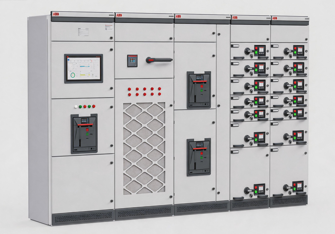
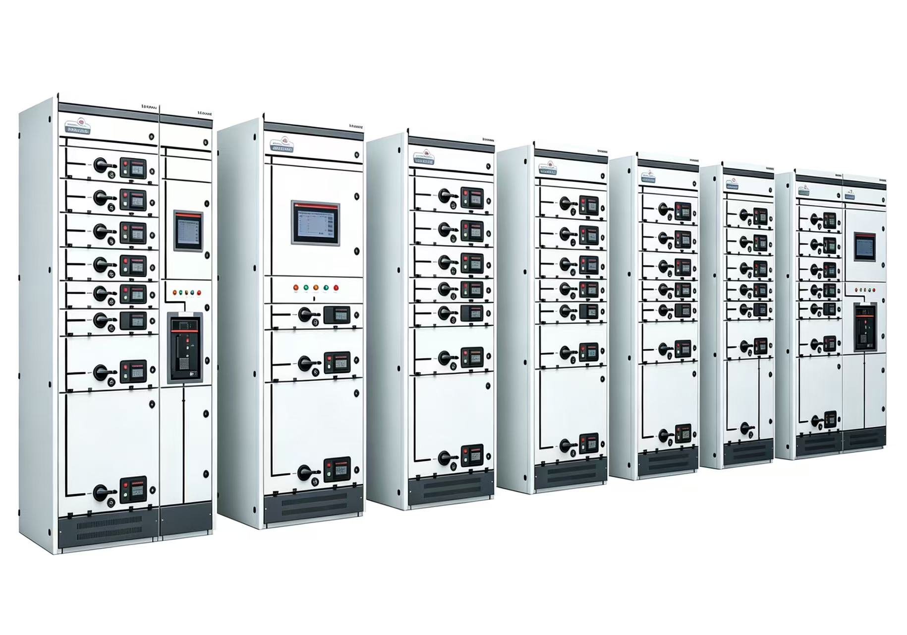
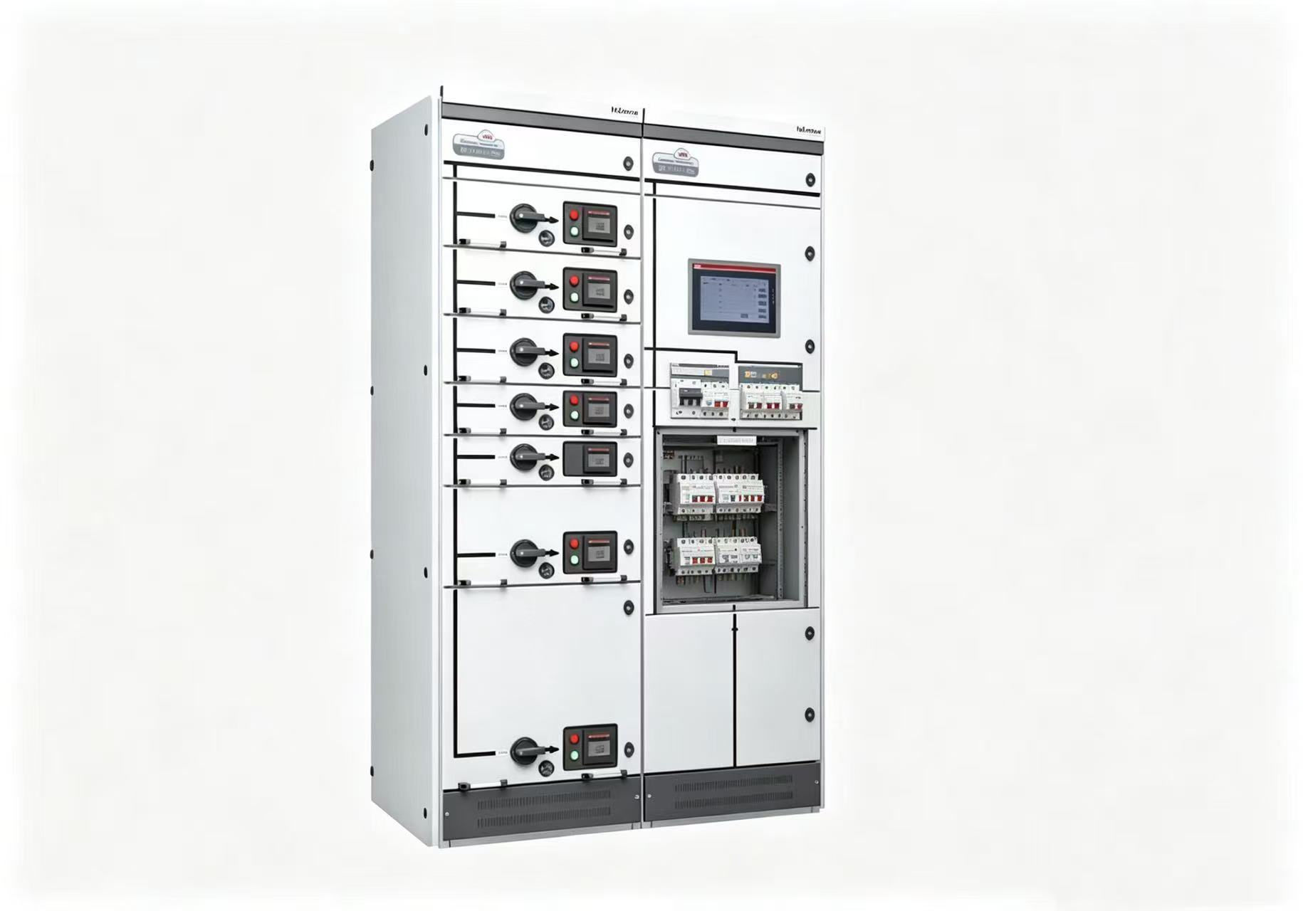
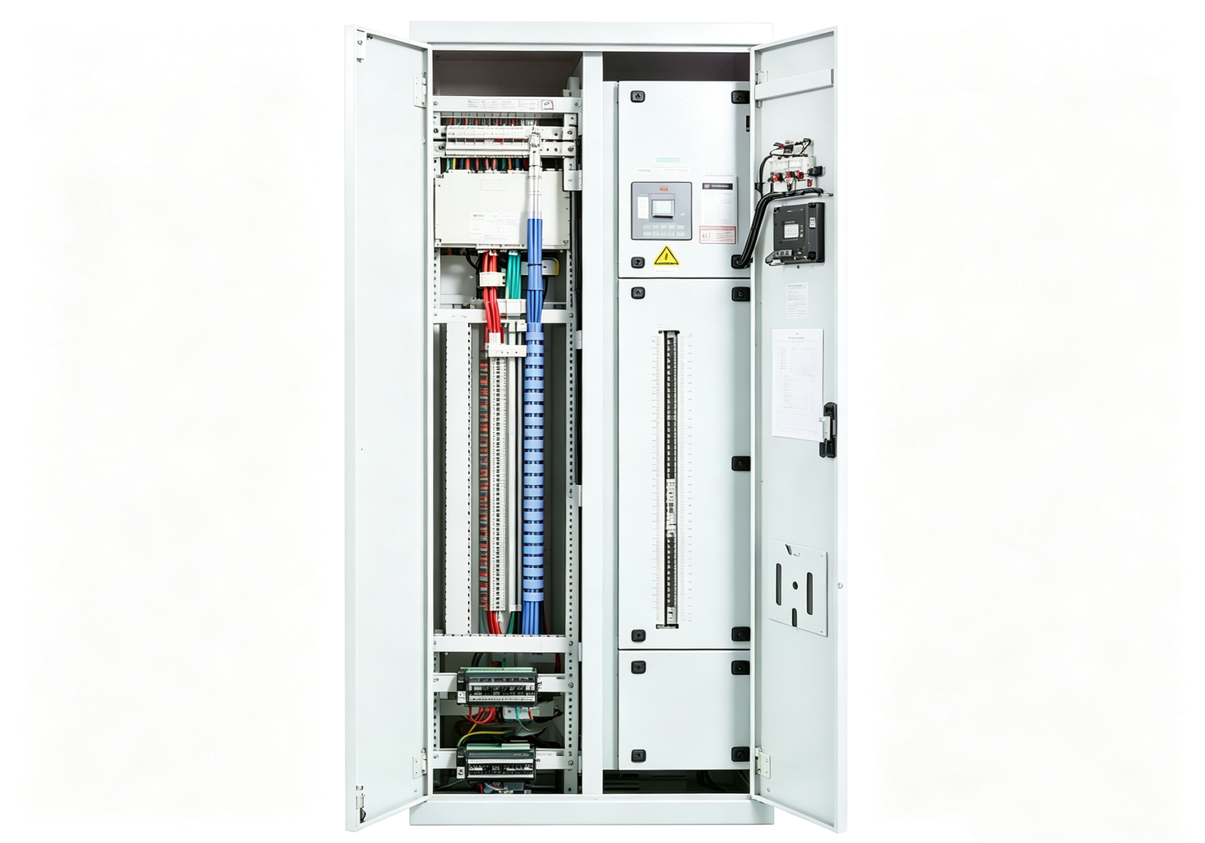

Lightning is one of nature’s most destructive phenomena — a single strike carries enough energy to power a city for minutes, and the transient overvoltages and massive currents it brings can be devastating to power distribution systems and electronic equipment. But many people’s understanding of lightning protection still stops at “put a lightning rod on the roof.” In reality, a complete lightning protection system is far more complex — it is a multi‑layer defence system that spans from the sky to the ground, from outdoors to indoors, and from high voltage to low voltage. This article walks you through the entire system: how external lightning protection “catches” the lightning current, how internal protection “blocks” the residual energy, and what that frequently misunderstood “ground resistance” should actually be.
Part One: External Lightning Protection — Three Lines of Defence Against Direct Strikes
The goal of external lightning protection is to “keep lightning out of the building.” It consists of three components: air terminals, down conductors, and grounding systems — collectively known as the “external lightning protection trio”.
First Line of Defence: Air Terminals — Actively “Catching” Lightning
Air terminals are what people commonly call “lightning rods,” but they are not just rods — they also include lightning strips and lightning mesh. Their function is not to “avoid” lightning but to actively “catch” the lightning current and direct it along a predetermined path into the ground, rather than letting it randomly strike through some corner of the building. The arrangement of air terminals follows strict regulations: Class I lightning‑protected buildings (such as chemical plants and explosive hazard areas) require independent lightning rods or overhead lightning wires/mesh, with mesh grid dimensions not exceeding 5m×5m; Class II and III buildings may use lightning strips laid along roof contours. Air terminals must be reliably connected to down conductors, and should be electrically connected to other exposed metal components near the roof.
Second Line of Defence: Down Conductors — The “Dedicated Channel” for Lightning Current
Down conductors are the conductors that connect air terminals to the grounding system, responsible for conducting the lightning current from the roof to the ground. The number and spacing of down conductors have specific requirements — when dedicated down conductors are used, there must be no fewer than 2, with spacing not exceeding 18m. Down conductors may utilise the main reinforcement bars in building columns, but must ensure continuous electrical continuity from top to bottom. Down conductors must be connected to each other and to the grounding system by welding or bolted connections.
Third Line of Defence: Grounding System — The “Final Destination” for Lightning Current
The grounding system is the network of conductors buried in the earth, responsible for safely dissipating the lightning current into the ground. Its core metric is ground resistance — the lower the resistance, the more smoothly the lightning current dissipates, the lower the ground potential rise, and the safer it is for equipment and personnel.
Part Two: Ground Resistance — What’s the Deal with That “4 Ohm” Figure?
Ground resistance is the most discussed and most misunderstood parameter in lightning protection systems. Different applications have entirely different requirements:
-
Lightning protection grounding (independent): ≤10Ω
-
Safety protection grounding (equipment enclosures): ≤4Ω
-
AC working grounding (transformer neutral): ≤4Ω
-
Repeated grounding (multiple neutral earth connections): ≤10Ω
-
Static discharge grounding: ≤100Ω
-
Flammable/explosive environments: ≤5Ω or even lower
For common grounding systems (where lightning protection, safety, and working grounding share a single earth electrode), the requirement is even more stringent — ground resistance must not exceed 1Ω. This is why many large buildings and precision equipment facilities require “ground resistance less than 1 ohm.”
Different classes of lightning‑protected buildings have different requirements for the impulse ground resistance of each down conductor: for Class I and II buildings, the impulse ground resistance of each down conductor must not exceed 10Ω; for Class III buildings, it must not exceed 30Ω.
Ground resistance is not “measure once, valid forever.” Soil resistivity changes with the seasons — lower in the rainy season, higher in the dry season — and ground electrodes corrode over time. Therefore, ground resistance needs to be measured periodically, especially before the annual thunderstorm season.
Part Three: Lightning Protection Zones (LPZ) — Dividing the Building into Areas with Different Safety Levels
The threat from lightning isn’t just “direct strikes” — more commonly, it’s “induced strikes”: lightning currents induce surge overvoltages in conductors, which propagate along power and signal lines into equipment. To provide targeted protection, international standard IEC 62305 divides areas into different “Lightning Protection Zones (LPZ)”:
-
LPZ 0A: Outside the building, completely unprotected. Subject to direct lightning strikes and full lightning electromagnetic fields.
-
LPZ 0B: Outside the building but within the protection range of air terminals. Not subject to direct strikes, but still exposed to full lightning electromagnetic fields.
-
LPZ 1: The first protected zone inside the building. Direct strikes are impossible, and surge currents are already partially limited.
-
LPZ 2: A deeper zone inside the building. Surge overvoltages are further reduced.
-
LPZ 3: Inside equipment enclosures or even higher‑level shielded zones, requiring further reduction of lightning electromagnetic pulses to protect the most sensitive equipment.
The significance of lightning protection zones is: at the boundaries between different zones, different grades of Surge Protective Devices (SPDs) are installed — from outdoor to indoor, from the main distribution cabinet to terminal equipment, progressively reducing the energy of the lightning current.
Part Four: Internal Lightning Protection — Graded SPD Configuration and Selection
SPDs are the core components of internal lightning protection. Their task is to clamp overvoltages to levels that equipment can withstand within an extremely short time (nanoseconds) when lightning overvoltages enter the building along power lines, and to divert surge currents to ground. SPDs are divided into three grades based on installation location and protection capability:
Grade 1 (T1 / Class B) — Installed at the Main Incoming Panel
This is the “front door” of lightning protection. Grade 1 SPDs must withstand the direct impact of direct lightning strikes or high‑energy induced surges, with the largest surge current capacity. Selection recommendations: Iimp (10/350μs waveform, representing direct strike energy) ≥12.5kA~25kA, or Imax (8/20μs waveform) ≥50kA~100kA. Residual voltage Up ≤2.5kV.
Grade 2 (T2 / Class C) — Installed at Sub‑Distribution Panels or Floor Distribution Boxes
This is the “middle gate” of lightning protection. After the Grade 1 SPD has dissipated the bulk of the energy, the residual induced surge energy is significantly reduced but still needs further suppression. Selection recommendations: Imax ≥40kA (8/20μs), Up ≤1.5kV.
Grade 3 (T3 / Class D) — Installed at Terminal Equipment Front‑End
This is the “last gate” of lightning protection. It protects the most sensitive terminal equipment such as PLCs, instrumentation, and communication devices. Selection recommendations: Up ≤1.2kV, with relatively smaller surge current capacity.
Three Core Parameters for SPD Selection:
Uc (Maximum Continuous Operating Voltage): The highest power‑frequency voltage the SPD can withstand continuously. If Uc is too low, the SPD ages faster; if too high, protection effectiveness is reduced.
Up (Residual Voltage / Voltage Protection Level): The voltage remaining across the SPD after it conducts. Up must be lower than the impulse withstand voltage (Uw) of the protected equipment — otherwise the equipment will still be damaged.
Surge Current Capacity (Iimp / Imax): The maximum lightning current energy the SPD can withstand. Different locations require different grades.
Two Critical Details in SPD Installation:
First, connecting conductors must be as short as possible, especially the earth lead. Conductors have inherent inductance, and lightning currents passing through them create inductive voltage drops — if the earth lead is too long, this voltage drop adds to the SPD’s residual voltage, resulting in a voltage actually applied to the equipment that is much higher than the SPD’s rated Up. This is the industry‑known “Kevin wiring” issue.
Second, a backup fuse or circuit breaker must be installed upstream of the SPD. When the SPD ages or fails short‑circuit, the backup protection cuts the circuit promptly to prevent fire.
Part Five: Equipotential Bonding — Eliminating “Potential Differences” at the Source
Another critical element of the lightning protection system is equipotential bonding — connecting all conductive metal parts (equipment enclosures, metal pipes, steel structures, cable shields, etc.) to the same earth potential.
Why is this necessary? When lightning strikes, the massive lightning current creates an instantaneous ground potential rise in the grounding system. If two pieces of equipment have different ground potentials, a dangerous potential difference appears between them — at best damaging communication interfaces, at worst endangering human life. Equipotential bonding balances the potential differences between different conductive parts, preventing extreme situations where “one device’s ground is 0V and another’s is 1000V” during lightning or fault conditions.
Equipotential bonding has three levels:
-
Main equipotential bonding: At the building entrance, all metal pipes, steel structures, and the grounding system are connected together.
-
Supplementary equipotential bonding: Within a local area, all conductive parts are connected together.
-
Lightning equipotential bonding: At the boundaries between lightning protection zones, metal objects and electrical systems crossing the boundary are bonded.
Part Six: Common Grounding System — Unifying “Separate Commands” into “Central Command”
In earlier designs, lightning protection grounding, safety grounding, and working grounding were often separate, with required separation distances between them (typically not less than 20m). But this “separate commands” approach is increasingly impractical in modern buildings — land is scarce, cabling is complex, and separate installation is costly.
Modern buildings widely adopt common grounding systems (also called combined grounding): all grounding functions are merged into a single grounding installation. The advantages of common grounding are: unified ground potential, no potential differences, and space and cost savings. The trade‑off is: the ground resistance requirement is more stringent — typically ≤1Ω.
A Complete Lightning Protection System — Every Part Is Essential
External lightning protection (air terminals + down conductors + grounding system) is responsible for “catching” direct strikes; lightning protection zones (LPZ) are responsible for “delineating” risk areas; graded SPD protection is responsible for “reducing” residual energy; equipotential bonding is responsible for “eliminating” potential differences; and the common grounding system is responsible for “unifying” the earth potential reference. These five elements form an interlocking chain — none can be omitted. If any one link fails, the entire lightning protection system can be compromised.
Next time you see a lightning rod on a roof, an SPD in a switchgear cabinet, or a test terminal in a ground testing pit, you’re not looking at isolated components — you’re looking at one part of a complete, carefully designed lightning protection system.