
NewsNEWCENTER
Featured products

Contact Us
Temperature Rise Calculation and Cooling Method Selection for Switchgear — From Heat Load to Cooling Solution
2026-10-02Temperature rise is the invisible timer for switchgear lifespan. Every 10°C rise in internal temperature roughly halves electronic component life. The essence of temperature rise control is balancing heat generation and heat dissipation. But many cabinets are designed with only breaker ratings and busbar ampacity calculated — the total internal heat load is never computed. This is the root cause of internal overheating and premature component aging.
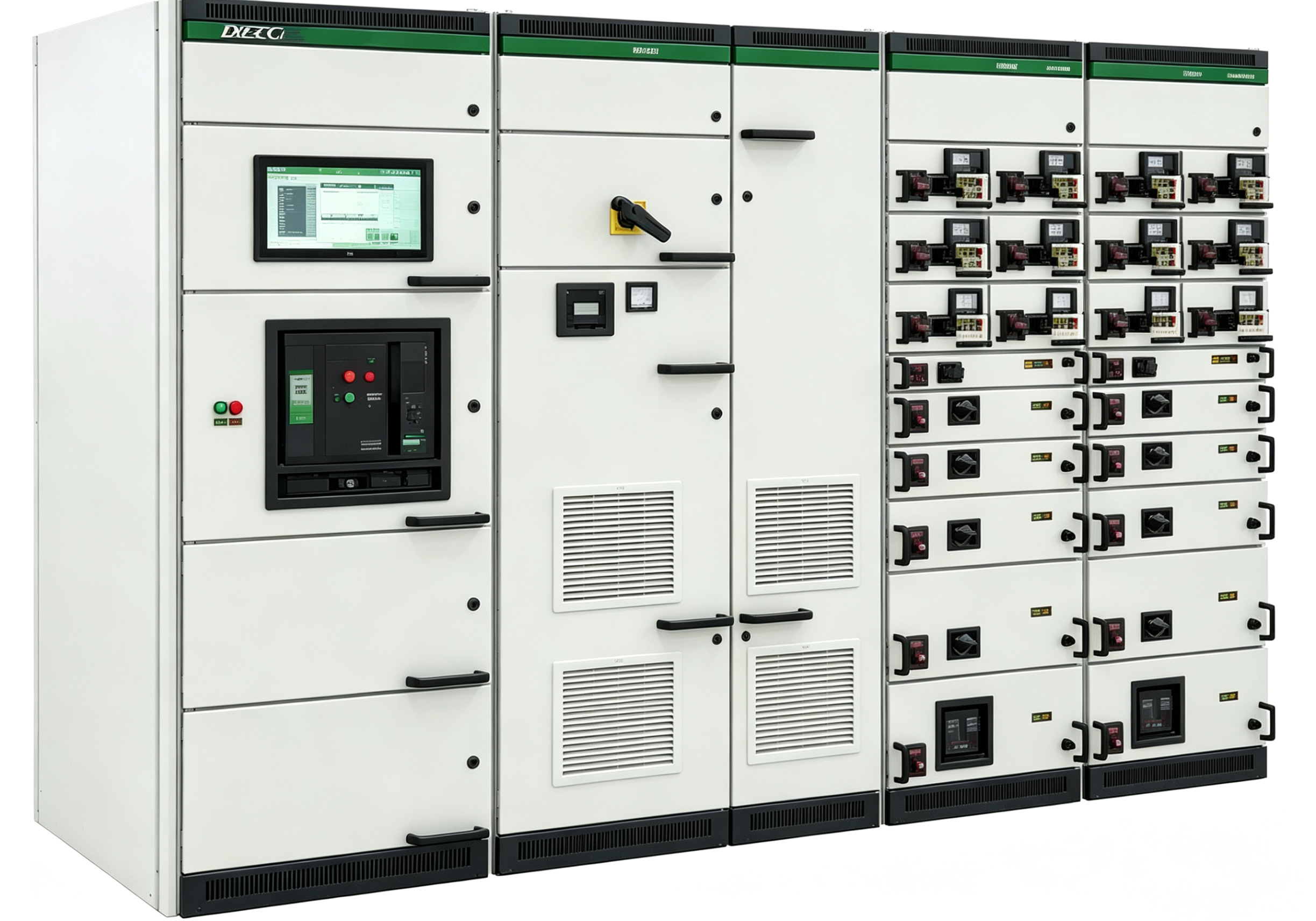
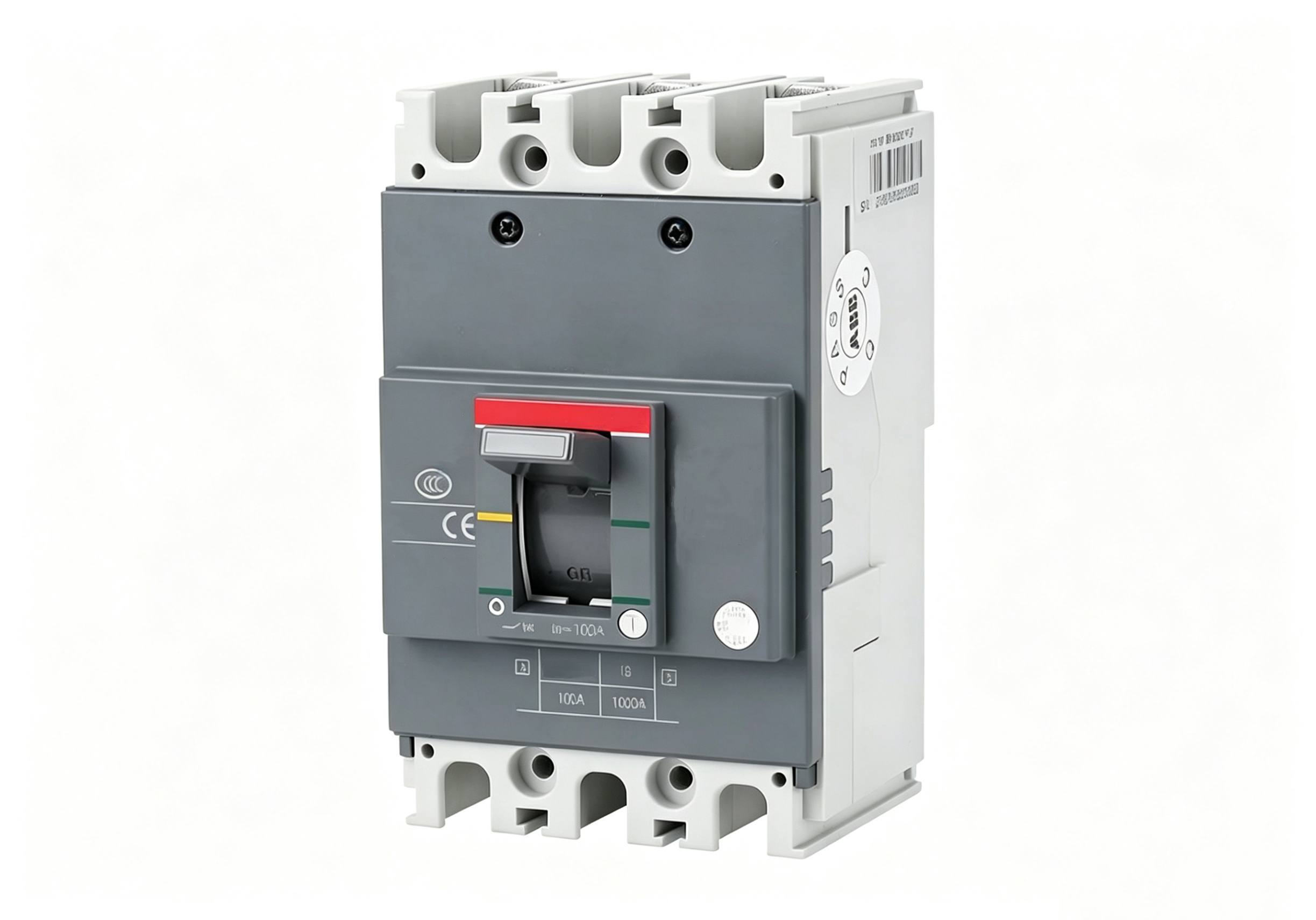
How to calculate heat load — don’t guess, look up data. Total internal heat load = sum of power losses of all heat‑generating components. Ptotal=P1+P2+…+Pn. Each component’s power loss must come from manufacturer technical data — not estimated from “experience percentages.” Typical heat sources and reference values: ACB about 5‑15W per pole; MCCB about 2‑8W per pole; contactor coils about 3‑10W; VFDs (by rated power) about 2%‑4% loss (a 75kW VFD at full load generates about 1.5‑3kW); soft starters similar; reactors about 1%‑2%; multi‑function meters about 2‑5W; PLCs about 5‑15W.
A fully loaded MCC cabinet (with 3 × 75kW VFDs, 10 contactors, 20 MCCBs) may have a total internal heat load of 5‑8kW. If this heat cannot be effectively removed, internal temperature rise may exceed 40K — far beyond design limits.
What are the temperature rise limits — IEC 61439 specifies. IEC 61439-1 (40°C ambient basis): busbar temperature rise ≤70K (busbar temperature ≤110°C), connection terminals ≤80K (≤120°C), accessible enclosure surfaces ≤30K (≤70°C), handles and operating parts ≤15K (≤55°C). For manually operated parts, limits are lower to account for operator comfort and safety.
How to choose a cooling method — start with one key number. The choice of cooling method depends on one key number: the difference between maximum permitted internal temperature and maximum ambient temperature. If this difference is comfortable (e.g., above 20K), natural ventilation or filter fans suffice; if ambient approaches or exceeds the internal target, no fan of any size will help — ventilation cannot supply air colder than ambient, and active cooling (air conditioning) or component reselection becomes necessary.
Natural ventilation: louvres top and bottom, outlet cross‑section at least 1.1 times inlet. Suitable for low heat generation (<500W) and low protection requirements. Forced fan cooling: suitable for medium heat generation (500W‑2kW) with some protection. But fans have finite life (typically 30,000‑50,000 hours) and draw dust into the cabinet; filters require regular replacement. Heat exchangers: isolate inside from outside, no external dust ingress, suitable for IP54 and above, medium heat generation (1‑3kW). But efficiency is lower than air conditioning, and internal heat exchange fins require periodic cleaning. Air conditioning: best cooling performance, suitable for high heat generation (>3kW) and high protection ratings (IP55 and above). But costly, has condensate issues, and requires regular drain maintenance.
Design points. Place heat‑generating components near the top of the cabinet to use natural convection; air inlets at the bottom, outlets at the top, avoiding short‑circuit airflow; VFDs and soft starters preferably in separate cabinets or near outlets; busbars vertical where possible for better convection; do not block ventilation openings or store items inside. For cabinets installed at high altitude or in high‑temperature environments, cooling design must be additionally derated — heat dissipation capacity decreases by about 8%‑10% per 1000m altitude.