
NewsNEWCENTER
Featured products

Contact Us
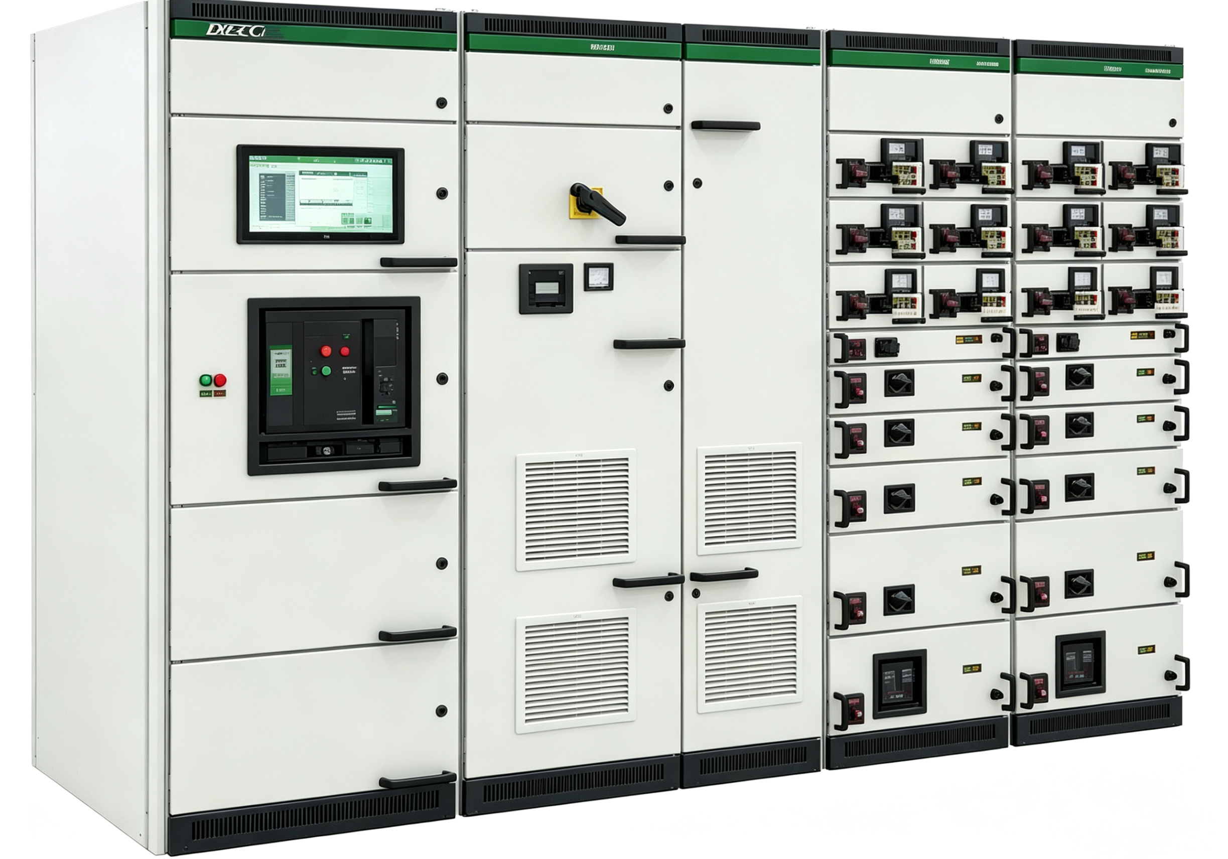
Factory Tests for Low-Voltage Switchgear — Items, Methods, and Acceptance Criteria
2026-10-02Factory testing is the “final checkpoint” before low-voltage switchgear is delivered. Every cabinet must undergo routine tests before shipment to confirm its performance meets design requirements and standards. But in reality, many factory test reports are “beautiful” yet the cabinet fails immediately on site — either test items were skipped, methods were wrong, or acceptance criteria were “relaxed.” This article clarifies the items, methods, and acceptance criteria for factory tests.
Insulation resistance test — the item most likely to be “perfunctory.” Insulation resistance testing is the first factory test item and the one most likely to be done superficially. Method: use a megohmmeter to measure insulation resistance of the main circuit phase-to-phase, phase-to-earth, and secondary circuit to earth. Acceptance criteria: low-voltage cabinet main circuit insulation resistance typically requires ≥0.5MΩ, but new cabinets should be far higher — main circuits typically ≥100MΩ, low-voltage equipment ≥1MΩ. When insulation resistance exceeds 10MΩ, a 2500V megohmmeter should be used; otherwise, 500V or 1000V. Key operational point: before testing, all electronic components (PLCs, meters, SPDs, VFDs) must be disconnected, otherwise the megohmmeter’s high voltage will directly damage them. This is the most common accident in factory testing — a perfectly good PLC “killed” by insulation testing.Power frequency withstand voltage test — verifying insulation strength. This is the core item for verifying insulation strength. Method: apply 2500V/1min to the main circuit (or the standard-specified test voltage), 1760V/1min to auxiliary circuits, leakage current <10mA, no breakdown or flashover. During testing, all electrical equipment should be connected, but coils, measuring instruments, and surge suppressors should be disconnected, as they cannot withstand the full test voltage. Acceptance criteria: no breakdown, no flashover, leakage current within specified limits. If a “crack” discharge sound is heard or flashover observed, insulation defects exist and must be investigated before retesting.
Protection device calibration — settings must match drawings. Protection device calibration ensures correct operation during faults. Method: verify settings of circuit breakers, thermal relays, and protection relays, confirming operating value errors within tolerance (typically ±10%). Common problem: protection devices shipped with “default values,” not re-set per design drawings; or set without verification, simply “writing pass.” During acceptance, protection device settings must be verified against design drawings, with on-site verification of operating values.
Functional tests — verifying operating logic. Functional tests verify the open/close, interlocking, signalling, and alarm functions of breakers, contactors, and interlocks. Method: simulate operation of each component, verifying operating logic matches design. For draw-out cabinets, verify that the drawer operates smoothly in “service,” “test,” and “disconnected” positions, and that interlocks are reliable. Five-prevention interlock functional testing is the most important functional test — actual operational verification is mandatory: with the breaker closed, the door should not open; with the earthing switch closed, the breaker should not close.
Temperature rise test — sampling or type test. Temperature rise testing verifies whether cabinet temperature rise exceeds limits at rated current. Method: apply rated current, run to thermal stability (temperature change <1°C/h), measure temperature rise of busbars and joints. Acceptance criteria: busbar temperature rise ≤70K, connection terminals ≤80K. Temperature rise testing is typically a type test or sampling item, not performed on every cabinet. However, for custom non-standard cabinets or high-heat MCC cabinets, temperature rise verification before shipment is recommended.
Wiring, connection, and earthing continuity checks. Check wiring practice, ferrule completeness, terminal tightness; verify earthing continuity between earthing terminals and protective circuits. Acceptance criteria: wiring horizontal and vertical, ferrules clear and matching drawings; earthing continuity resistance meets standard requirements.How to judge the “value” of a factory test report. A qualified factory test report must include: test date, ambient temperature, humidity, test equipment number and calibration validity, tester signature, and raw data records. If the report has only the word “pass,” no raw data, no equipment number, and no signature — the report’s “value” is zero. During acceptance, the client or supervisor should witness critical items (insulation, withstand voltage, protection settings) on site, not just stamp the paper.