
NewsNEWCENTER
Featured products

Contact Us
Busbars and Insulation Supports in Low-Voltage Switchgear — From Ampacity Correction to Short-Circuit Electrodynamic Calculation
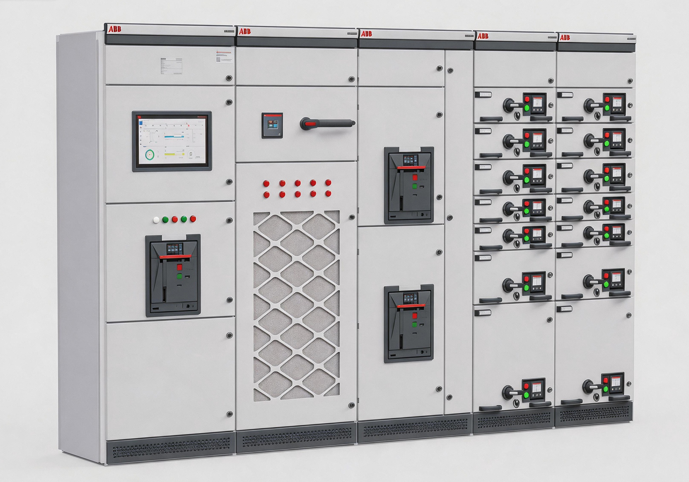
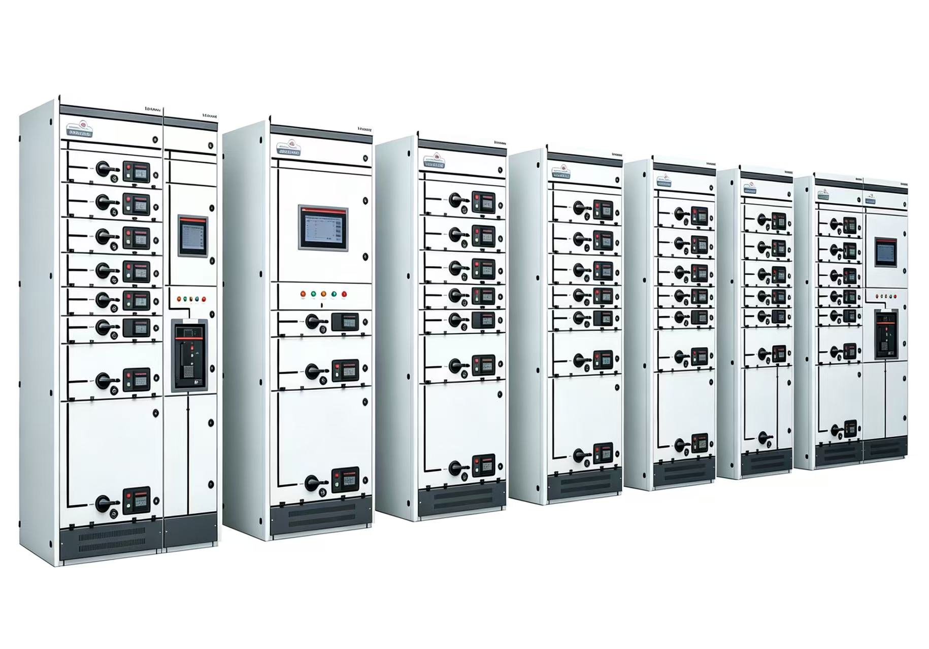
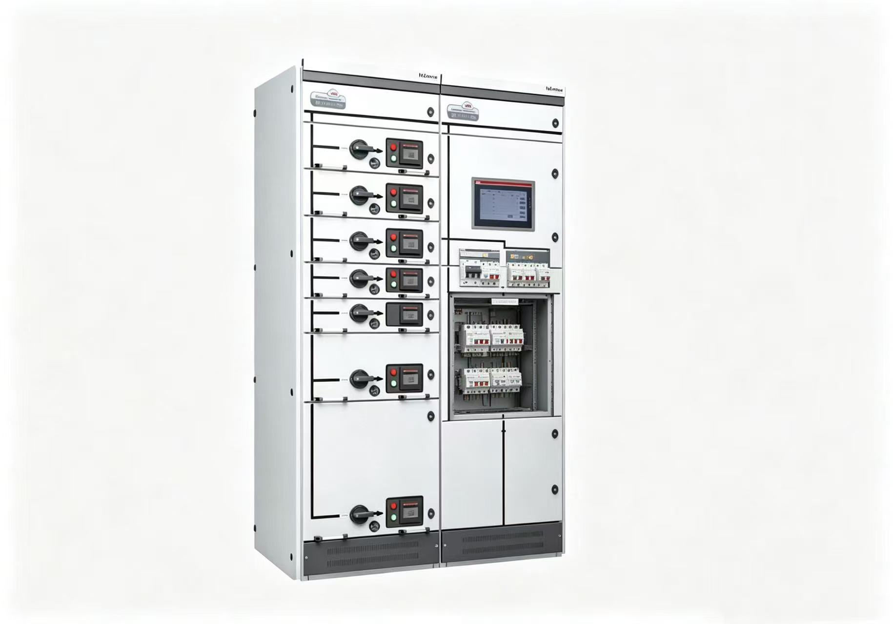
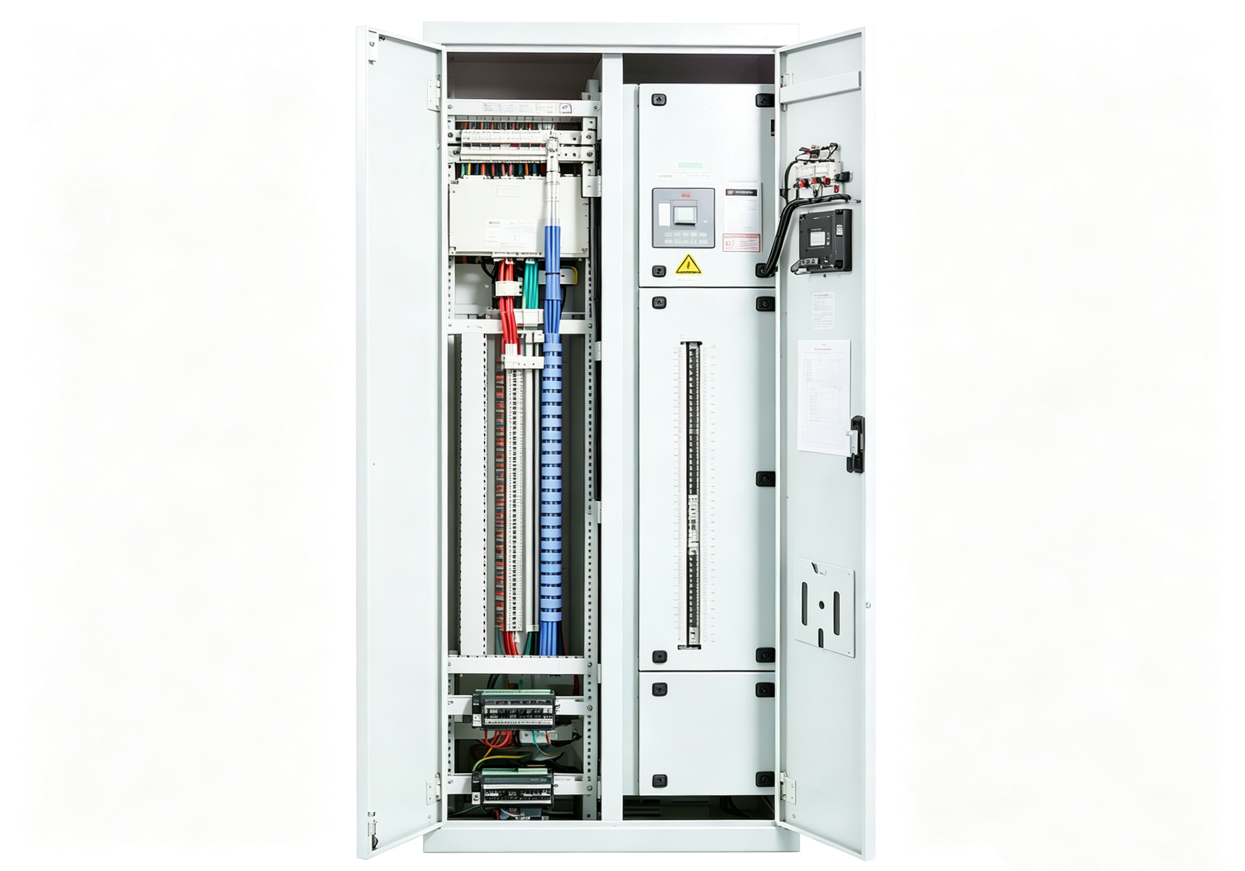
2026-10-02The busbar is the main artery of low-voltage switchgear, and the insulation support is the skeleton that holds this artery in place. Many engineers select busbars by looking up a single ampacity table and select insulators by “whether it fits,” completely overlooking the three decisive parameters — correction factors, short-circuit electrodynamic forces, and support spacing. Undersized busbars lead to excessive temperature rise and accelerated insulation aging; undersized insulation supports allow busbar deformation and insulator fracture during short circuits, potentially causing phase-to-phase short-circuit explosions.
Ampacity correction — three factors multiplied, table value may drop to 60%. Busbar ampacity tables are typically based on 25°C ambient, altitude below 1000m, vertical orientation, and bare-bar installation. Multiple correction factors must be applied in practice. The temperature correction factor is Kt=(70−T)/(70−25), where 70°C is the maximum allowable copper bar temperature. At 30°C, Kt≈0.94; at 40°C, Kt≈0.82; at 50°C, Kt≈0.67. The altitude correction factor is Kh=1−0.005×(H/1000) (H ≤ 4000m). At 2000m, Kh=0.99; at 4000m, Kh=0.98 — altitude’s effect appears small but compounds with temperature correction. The correction factor for enclosed cabinet installation is about 0.8–0.85, and vertical orientation carries 10%–15% more current than horizontal.
Consider a cabinet rated 630A, 40°C ambient, enclosed cabinet, vertical orientation. A 50×5 copper bar rated 630A at 25°C vertical: multiply by 0.82 (temperature) = 517A; multiply by 0.85 (enclosed) = 439A — far below 630A. A larger size is required, such as 80×6 (about 1100A at 25°C vertical), corrected to 1100 × 0.82 × 0.85 ≈ 767A — sufficient for 630A. This is why “look up the table and pick a busbar” often fails — three correction factors multiplied together can reduce ampacity to 60%–70% of the table value.
Parallel busbar derating and uneven current distribution. When multiple busbars are paralleled, adjacent bars heat each other, and each bar’s actual ampacity must be derated. Two bars in parallel use a factor of 0.9, three bars 0.85, four bars 0.8. Moreover, the more bars in parallel, the more uneven the current distribution — due to skin effect and proximity effect, outer bars carry more current while inner bars carry less. Selecting based on “total current ÷ number of bars” means inner bars run underloaded and outer bars overloaded, accelerating aging. For critical circuits, it is recommended to measure the current distribution of each bar; when deviation exceeds 15%, adjust the bar arrangement or increase the number of bars.
Short-circuit electrodynamic calculation — the life-or-death line for insulation support spacing.This is the most easily overlooked step. During a short circuit, enormous electrodynamic forces act between busbars. The force is proportional to the square of the peak short-circuit current and inversely proportional to the busbar centre distance.
For a three-phase short circuit, the middle phase experiences the greatest force. Based on peak withstand current Ip, the force per unit length is F=0.173×K×Ip2/a (N/m), where K is the shape factor (typically 1 for rectangular busbars) and a is the busbar centre distance (mm).
Consider a cabinet with busbar centre distance a = 100mm and peak withstand current Ip = 105kA (corresponding to 50kA short-time withstand current): F=0.173×1×1052/100≈19.1 N/mm = 19,100 N/m. That is, each metre of busbar experiences about 1.9 tonnes of force. If the insulation support spacing is 1m, the bending moment on a single insulator is the effect of 1.9 tonnes × 1m lever arm — ordinary insulators cannot withstand this.
Insulation support spacing must satisfy both dynamic and thermal stability requirements. Empirical values in engineering practice: for 50kA short-circuit current, spacing should not exceed 500mm; for 80kA, not exceed 350mm. GGD cabinet busbar insulator support spacing generally does not exceed 1m; for systems with larger short-circuit capacity, spacing must be reduced or reinforced insulators used.
Hard specifications for insulation support selection. Insulators must withstand not only short-circuit electrodynamic forces but also busbar self-weight, thermal expansion and contraction stresses, and long-term environmental factors (temperature, humidity, pollution).
For materials, low-voltage cabinets commonly use epoxy resin cast insulators or DMC (dough moulding compound) insulators. Epoxy insulators offer high mechanical strength and good arc resistance, suitable for high short-circuit current applications; DMC insulators are lower in cost, suitable for general applications. Selection must verify the insulator’s rated bending failure load — typically requiring a safety factor of not less than 2 times the calculated short-circuit electrodynamic force.
For creepage distance, the insulator’s height and shed count determine creepage distance. In pollution degree 3 environments, the insulator’s creepage distance must meet GB/T 7251.1 requirements — not just “is the height enough.”
Acceptance and inspection points. During acceptance, use a 0.05mm feeler gauge on busbar joints; insertion depth must not exceed 5mm. Use a torque wrench to verify bolt tightening torque (M8 about 20–25 N·m, M10 about 35–40 N·m, M12 about 45–50 N·m). Use callipers to measure insulation support spacing against design requirements. During inspections, use an infrared thermometer to scan busbar joints and insulator surfaces — when temperature difference exceeds 15°C or insulator surface temperature is significantly above ambient, further investigation is required.