
NewsNEWCENTER
Featured products

Contact Us
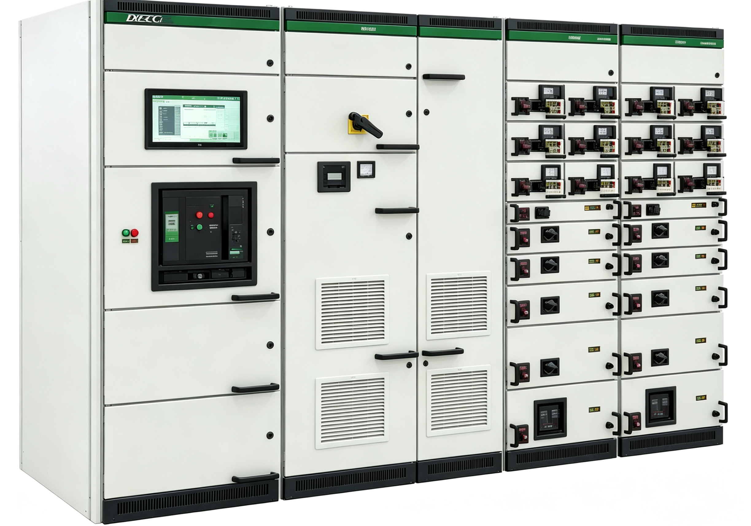
Five-Prevention Interlocking in Low-Voltage Switchgear — How Mechanical and Electrical Interlocks Work Together
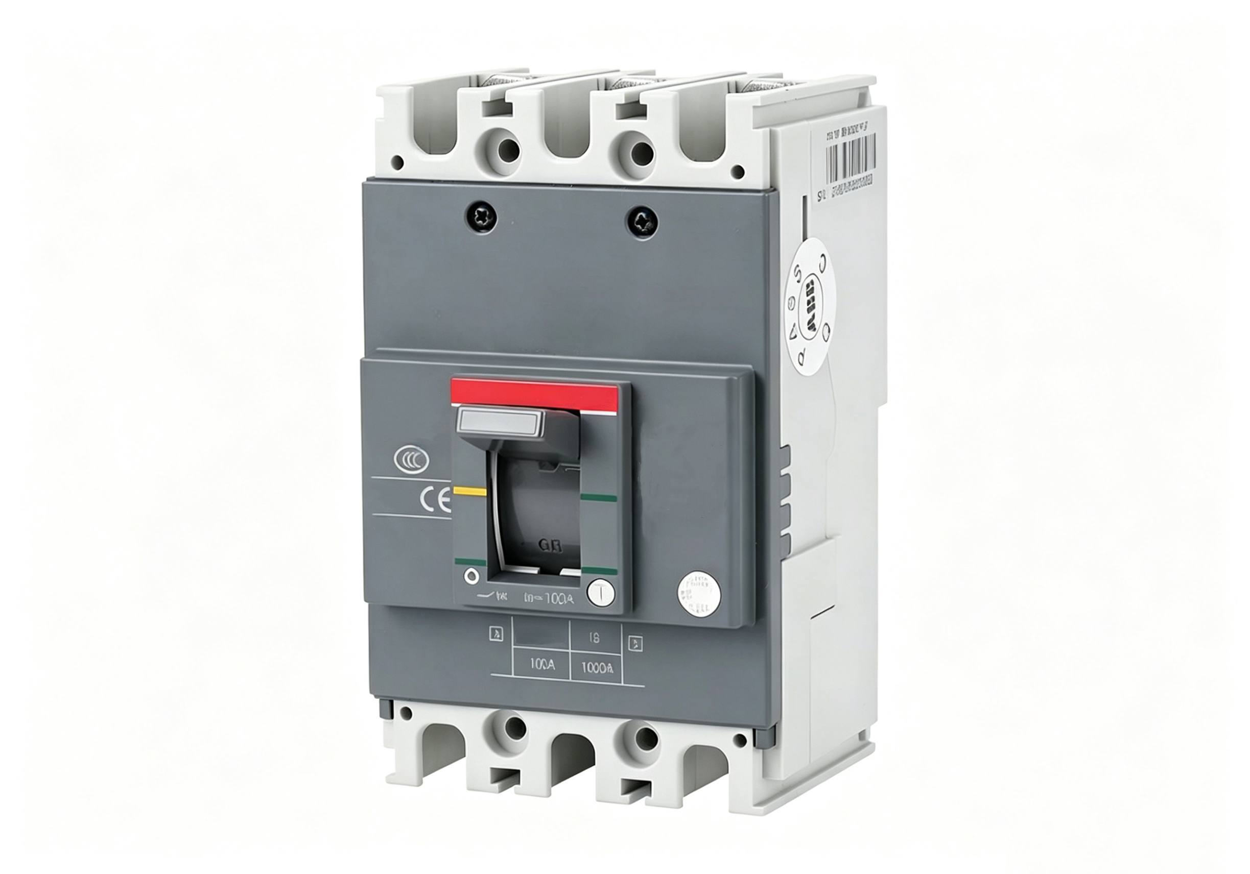
2026-10-02The most critical safety function of low-voltage switchgear is not how good the circuit breakers are or how thick the busbars are — it is whether the interlocking system can prevent misoperation. A well-designed interlocking system physically blocks wrong operations before the operator makes a mistake — you cannot close a breaker you shouldn’t, you cannot rack a carriage you shouldn’t, you cannot open a door you shouldn’t. This is the essence of the “five preventions”: replacing human diligence with hardware logic.
What exactly do the five preventions prevent? The five-prevention requirements for low-voltage switchgear are: preventing incorrect opening or closing of circuit breakers; preventing opening or closing disconnectors (or isolating plugs) under load; preventing closing of earthing switches (or attaching earth cables) while energised; preventing energisation with earthing switches (or earth cables) closed; and preventing entry into live compartments. Different sources express the specifics slightly differently, but the core logic is entirely consistent — using interlocking devices to enforce mandatory operating sequences
Mechanical interlocking: physical barriers, independent of power. Mechanical interlocking is the most reliable and fundamental interlocking method in low-voltage switchgear. It relies on the mutual restraint of mechanical components — latches, shutters, linkages, keys — independent of external power and unaffected by power outages.
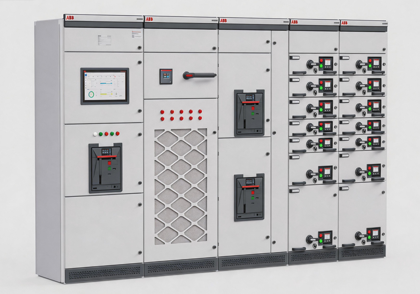
Typical mechanical interlocking logic for draw-out units: the drawer has “service,” “test,” and “disconnected” positions. The drawer can only be racked when the circuit breaker is open — achieved through the mechanical coordination of the operating shaft and racking mechanism. In the service position, the drawer cannot be directly withdrawn; only when racked to the test position can secondary circuits be tested, with primary contacts separated from the main busbar; only after racking to the disconnected position can the drawer be withdrawn
Door interlocking is another key application: when the circuit breaker is closed, the door cannot be opened — the operating shaft is mechanically linked to the door lock. Only after the breaker opens is the lock released. For cable compartment rear doors, interlocking with the earthing switch is typical: only after the earthing switch is closed and the key released can the rear door be opened.
Key transfer interlocking is a higher-level mechanical interlocking form. Multiple keys are logically transferred to control the operating sequence: the key from the incoming cabinet is required to unlock the transformer cabinet door, enforcing strict procedural operation. This type is particularly suitable for complex distribution systems requiring sequential operation.
Electrical interlocking: flexible programming logic. Electrical interlocking is implemented through auxiliary contacts, intermediate relays, and PLC/controllers, suitable for complex, remote, or non-directly-mechanical scenarios
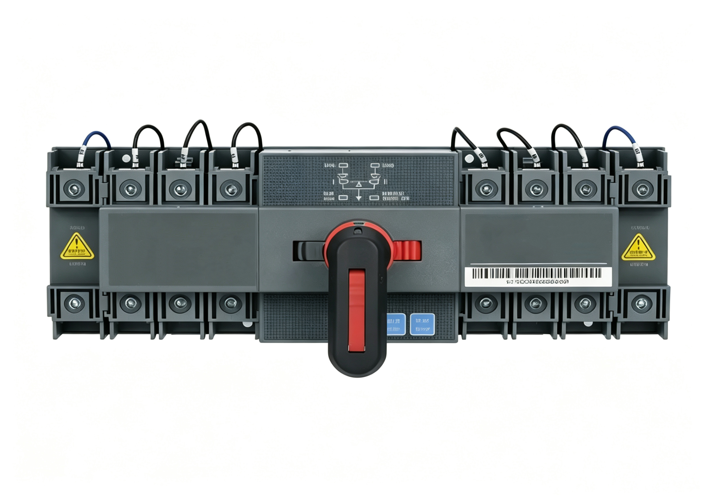
Multi-supply incoming interlocking is the most typical electrical interlocking application: ensuring that among two incoming breakers and a bus-tie breaker, at most two can be closed simultaneously, preventing parallel operation. If both incomings are closed, the bus-tie must be forced open; if the bus-tie is closed, only one incoming can be closed.
VFD/utility frequency switching is another common scenario: ensuring contactors KM1 and KM2 never close simultaneously, preventing phase-to-phase short circuits. Electrical interlocking uses auxiliary contact logic: when KM1 is energised, its normally closed contact opens KM2’s coil circuit, and vice versa.
Best practice: mechanical primary, electrical secondary, double insurance. The best practice for any interlocking design is combined use of mechanical and electrical interlocking, with mechanical as primary and electrical as secondary. Mechanical interlocking provides “hard constraints” — regardless of electrical circuit failures, the physical barrier remains. Electrical interlocking provides “soft logic” — covering complex logic scenarios that mechanical interlocking cannot reach.
Using steel wire for interlocking is strictly prohibited. Carriage position contacts used in interlocking circuits must only close when the carriage contacts and switchgear fixed contacts have sufficient safety clearance. Shutter (safety barrier) drives must have a locking mechanism so that when the carriage is withdrawn, the shutter closes and cannot be accidentally opened.
How to verify interlocks during acceptance. Interlock acceptance cannot rely on “reading the manual.” Actual operational verification is mandatory: with the breaker closed, attempt to open the door — it should not open; attempt to rack the drawer — it should not rack; with the earthing switch closed, attempt to close the breaker — it should not close. Every interlocking logic must be verified by actual operation, not signed off on the basis of “it looks like interlocks are installed.”